
Tray type card connector
a card connector and tray-type technology, applied in the direction of conveying record carriers, coupling device connections, instruments, etc., can solve the problems of card connectors not being compatible with waterproof devices, card tray cannot be easily ejected, etc., and achieve the effect of reducing the number of components and being easy to pull ou
Patent Information
- Authority / Receiving Office
- US · United States
- Patent Type
- Applications(United States)
- Current Assignee / Owner
- Publication Date
- 2015-06-04
Smart Images
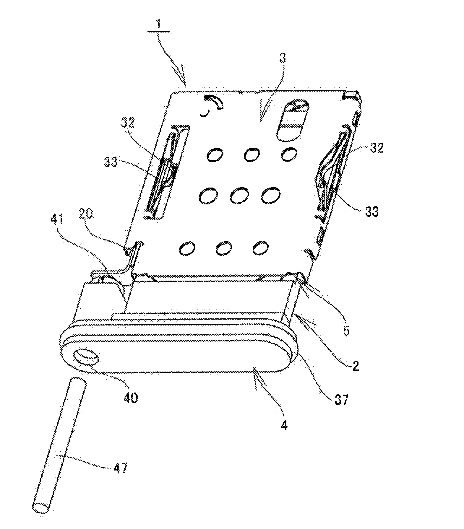
Figure 1 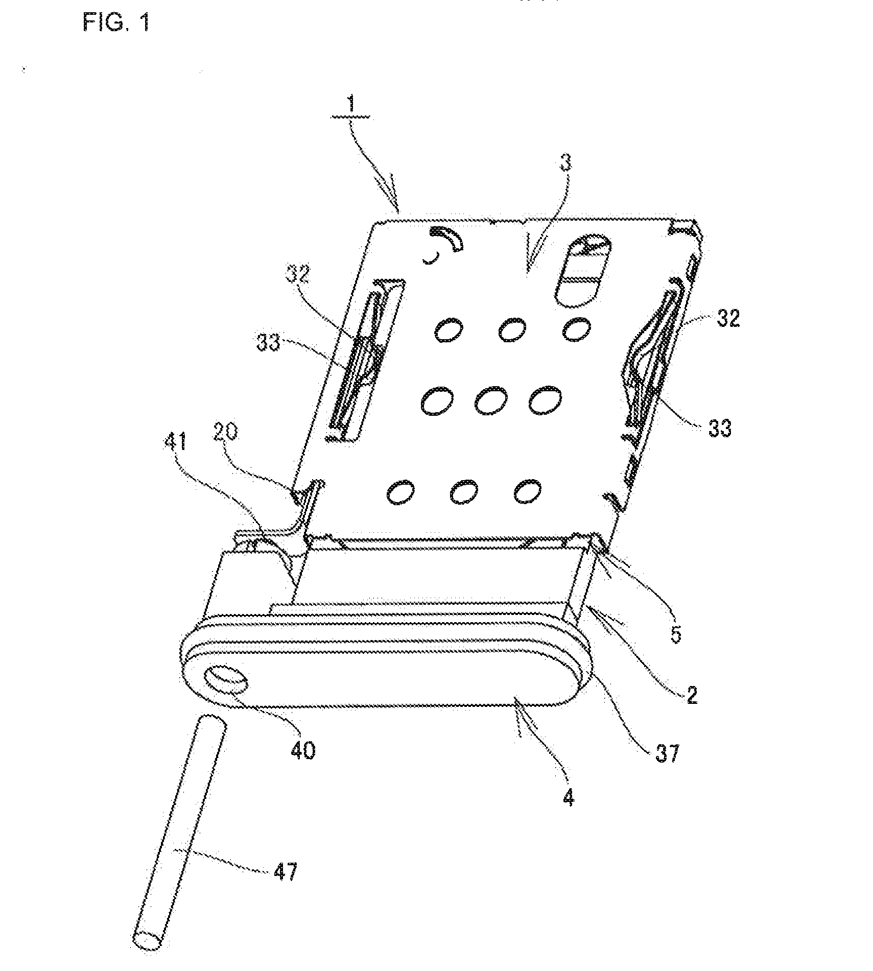
Figure 2 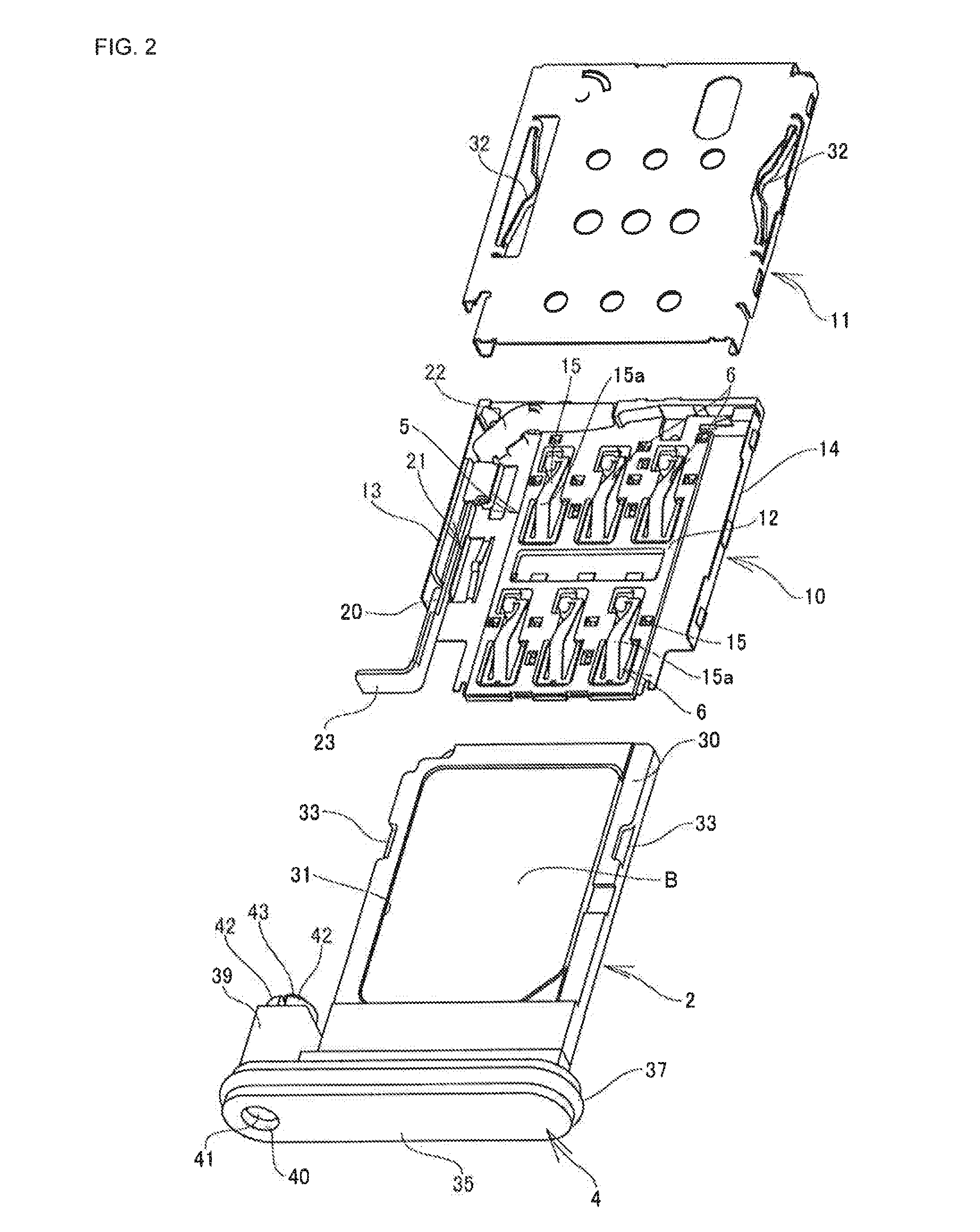
Figure 3
Abstract
Description
CROSS-REFERENCE TO RELATED APPLICATION
[0001] This application claims priority of Japanese Patent Application No. 2013-249878 filed Dec. 3, 2013, which is incorporated herein by reference in its entirety.BACKGROUND
[0002] 1. Technical Field
[0003] The present invention relates to a card connector for connecting a card such as an IC card or a flash memory card into a mobile phone, a smartphone, or other electronic devices. More particularly, the present invention relates to a tray type card connector compatible with waterproof electronic devices.
[0004] 2. Related Art
[0005] Conventionally, for an external storage medium for an electronic device such as a mobile phone or a smartphone, a card such as an IC card or a flash memory card is used. The card and a printed wiring board installed in the electronic device are electrically connected to each other through a card connector.
[0006] There is known a card connector that includes a housing disposed in an electronic device; a card tray that is ins...
Examples
first embodiment
[0037]Next, a tray type card connector 1 according to the present invention will be described based on an implementation example shown in FIGS. 1 to 6.
[0038]Note that in the drawings reference sign A indicates an electronic device such as a mobile phone or a smartphone, and reference sign B indicates a card such as an IC card. Note also that in the present implementation example a description is made with the front side in a card tray insertion and removal direction being “front” and the back side being “rear”.
[0039]The electronic device A is structured such that the tray type card connector 1 is used for connection of the card B such as an IC card, and by inserting and removing a card tray 2 into / from the electronic device A through a casing opening portion Aa opened at a lateral surface portion of a casing of the electronic device A, the card B can be mounted and demounted on / from a housing 3 disposed in the electronic device A, and the casing opening portion Aa can be closed by a...
second embodiment
[0071]Next, a tray type card connector according to the present invention will be described based on an implementation example shown in FIGS. 7 to 10A and 10B. Note that a description is made denoting the same components as those of the above-described implementation example by the same reference signs, and reference sign A indicates an electronic device and reference sign B indicates a card.
[0072]This tray type card connector 50 includes a card tray 51 where the card B is held; a housing 53 having a tray insertion portion 52 into which the card tray 51 is inserted; and a plurality of contacts 54, 54 . . . arranged in the housing 53 so as to project within the tray insertion portion 52. By inserting the card tray 51 into the housing 53 through a casing opening portion Aa, pad portions b1, b1 . . . of the card B held in the card tray 51 come into contact with the corresponding contacts 54, 54 . . . , by which the card B is electrically connected to a substrate having the card connect...