
Pneumatic Tire
a pneumatic tire and tread technology, applied in the field of pneumatic tires, can solve the problems of reduced rigidity of the tread portion, decreased drainage performance, and decreased steering stability on dry road surfaces, and achieve the effects of ensuring steering stability, good steering stability, and ensuring the rigidity of the land portion
Patent Information
- Authority / Receiving Office
- US · United States
- Patent Type
- Applications(United States)
- Current Assignee / Owner
- Publication Date
- 2019-01-31
Smart Images
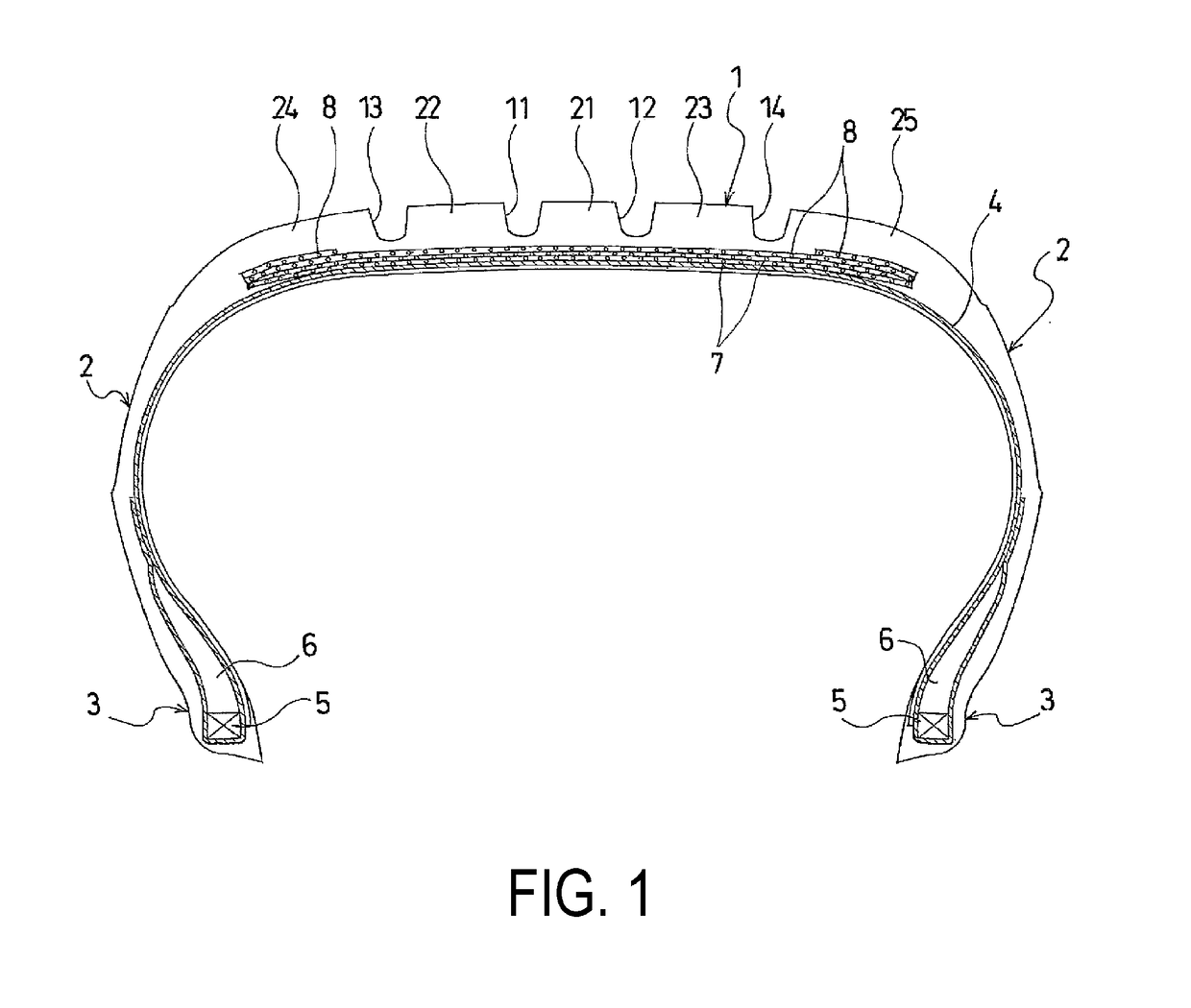
Figure 1 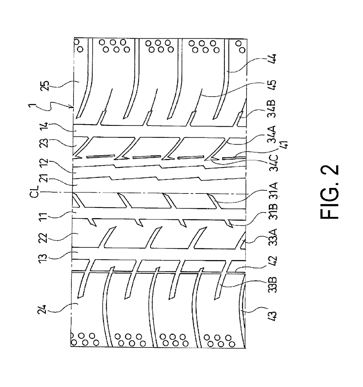
Figure 2 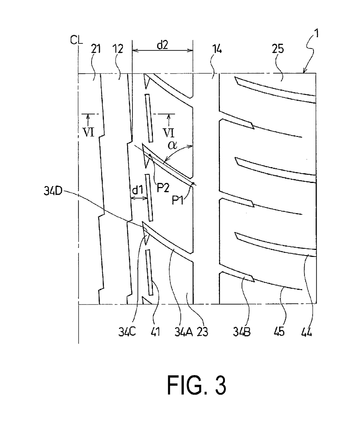
Figure 3
Abstract
Description
TECHNICAL FIELD
[0001] The present technology relates to pneumatic tires including center main grooves extending in a tire circumferential direction, shoulder main grooves extending in the tire circumferential direction on the outside of the center main grooves, and land portions extending in the tire circumferential direction between the center main grooves and the shoulder main grooves in tread portions, and more specifically, relates to pneumatic tires that have improved uneven wear resistance while achieving good steering stability on dry road surfaces and wet road surfaces, which are in a negative correlation, in a compatible manner by appropriately setting configurations of tread patterns.BACKGROUND ART
[0002] Pneumatic tires use a tread pattern in which a plurality of main grooves extending in a tire circumferential direction and rows of land portions defined by the main grooves are formed in a tread portion (for example, see Japanese Unexamined Patent Publication No. 2012-228992...
Examples
Embodiment Construction
[0019]The configuration of the present technology is described in detail below with reference to the accompanying drawings. FIGS. 1 to 6 illustrate a pneumatic tire according to an embodiment of the present technology.
[0020]As illustrated in FIG. 1, a pneumatic tire of the present embodiment includes an annular tread portion 1 extending in the tire circumferential direction, a pair of sidewall portions 2, 2 disposed on both sides of the tread portion 1, and a pair of bead portions 3, 3 disposed inward of the sidewall portions 2 in the tire radial direction.
[0021]A carcass layer 4 is mounted between the pair of bead portions 3, 3. The carcass layer 4 includes a plurality of reinforcing cords extending in the tire radial direction and is folded back around bead cores 5 disposed in each of the bead portions 3 from a tire inner side to a tire outer side. A bead filler 6 having a triangular cross-sectional shape formed from rubber composition is disposed on a periphery of the bead core 5...