
Connector for flat conductive path
a technology of connecting wires and conductive paths, applied in the direction of fixed connections, coupling contact members, coupling device connections, etc., can solve the problem of adversely affecting the reliability of the connection
Patent Information
- Authority / Receiving Office
- US · United States
- Patent Type
- Patents(United States)
- Current Assignee / Owner
- Publication Date
- 2000-03-28
- Estimated Expiration
- Not applicable · inactive patent
Smart Images
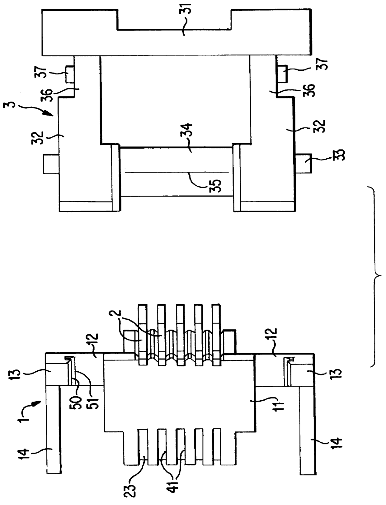
Figure 1 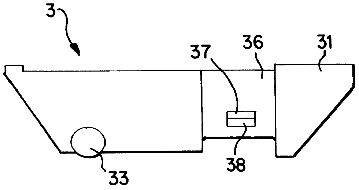
Figure 2 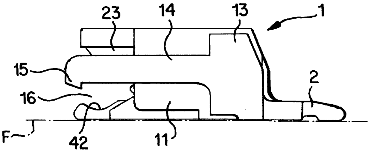
Figure 3
Abstract
Description
The present invention relates to an electrical connector to which a sheet-like electrically conductive path is attachable.BACKGROUND TO THE INVENTIONA well-known example of a connector for a strip or sheet-like electrically conductive path is disclosed in the Laid-Open Publication Tokkaihei 8-279378. As shown in FIGS. 10 and 11 of this specification, a ribbon cable connector is provided with a plurality of terminals a housed in a parallel manner within a connector housing b, and a cover c which can be opened to a releasing position or closed to a pressing position with respect to the connector housing b. When the cover c is in the releasing position, a ribbon cable d can be inserted between the cover c and the terminal a. This ribbon cable d is clamped between the cover c and the terminal a when the cover c is closed to the pressing position, thus electrically connecting the ribbon cable d with terminal a. Locking members e and f are provided on the cover c and the housing b in orde...
Examples
Embodiment Construction
An embodiment of the present invention is described below with the aid of FIGS. 1 to 9.
As shown in FIG. 1, a connector comprises a connector housing 1, a plurality of terminals 2 attached to the housing 1, and a pressing member 3 attached in a pivotable manner to the housing 1. A sheet-like electrically conductive path suitable for use in this embodiment is a ribbon cable 4 comprising a flexible printed circuit or FPC (see FIG. 10), and has a configuration whereby the upper face of a bendable sheet-like base member has a plurality (five in the present embodiment) of evenly spaced conductive paths (not shown) formed thereon by a print distributing means, the anterior end of each conductive path making contact with contact members 24 of the terminals 2.
The housing 1 is formed in a unified manner from synthetic resin and, as shown in FIGS. 1 and 2, has a block-like main body 11. As shown in FIG. 3, protruding members 12 protrude to the left and right sides from the lower portion of the...