
Electric rotary grater
a rotary grater and electric technology, applied in the field of graters, can solve the problems of difficult and tiresome handling, inapplicability of manual methods to produce large quantities of powder, and limited powder production, and achieve the effect of quick grating and fun for chucking food into powder, and prolonging the life of its us
Patent Information
- Authority / Receiving Office
- US · United States
- Patent Type
- Patents(United States)
- Current Assignee / Owner
- Publication Date
- 2005-11-22
- Estimated Expiration
- Not applicable · inactive patent
Smart Images
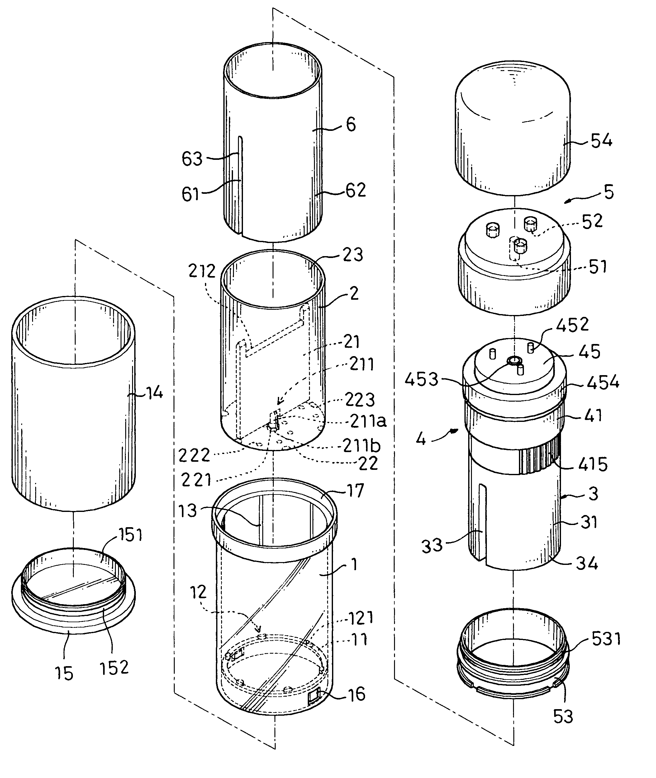
Figure 1 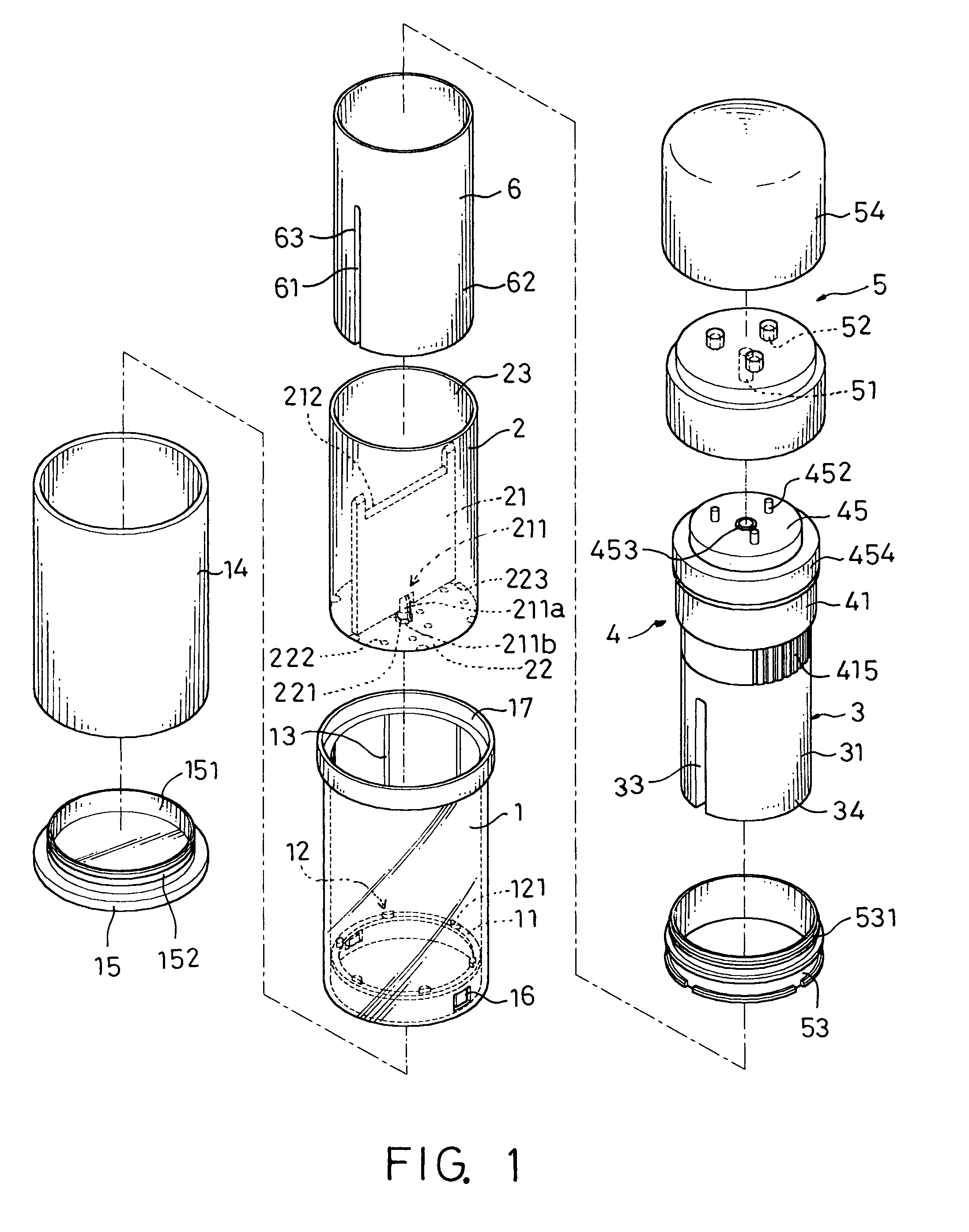
Figure 2 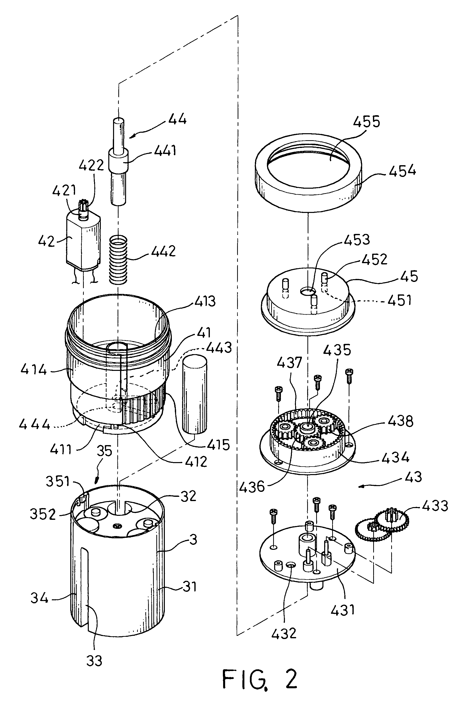
Figure 3
Abstract
Description
BACKGROUND OF THE INVENTION
[0001] 1. Field of the Invention
[0002] The present invention relates to a grater, more particular to an electric rotary grater.
[0003] 2. Description of the Related Art
[0004] In western cuisines, chunks of cheese or chocolate are generally grated into powder and spread onto food to give better flavors to the food. The common graters usually have grater holes stamped out from a piece of metal plate, and the food is held by a hand and grated back and forth on the grater into powder. However, such manual method is not applicable for producing a large quantity of powder.
[0005] Therefore, grater manufacturers started developing electric graters to grate cheese or chocolate into powder in a more efficient and quicker way. The “KRUPS” branded cheese grater is an example of such electric grater. However, the shortcoming of an electric grater resides on that the opening of the feeder is too small, and food must be sliced first before being put into the feeder for the gra...
Examples
Embodiment Construction
[0013]Refer to FIGS. 1 to 3 for the grater of the present invention, which comprises an external cylinder 1, a roller 2, a power device 3, a transmission device 4 and a top cover 5.
[0014]The external cylinder 1 is a hollow cylinder having a blocking edge 11, a positioning mechanism protruded from the bottom of an inner wall of the external cylinder 1 as shown in FIG. 1 and a plurality of tenons 12 protrude from the blocking edge 11 for coupling with the grooves 223 at the periphery of a grater disc 22. The grate disc 22 is fixed onto the bottom of the external cylinder 1. To reduce the friction between the inner walls of the external cylinder 1 and the roller 2, a plurality of transversal ribs 13 are built on the inner wall, so that the roller 2 can rotate smoother. In addition, a metal pipe such as an external stainless steel pipe is sheathed onto the exterior of the external cylinder 1 to enhance the external texture of the grater of the present invention. Further, a bottom chassi...