
Digital exciter/phasor/transmitter for directional antennal system
a digital exciter and directional antenna technology, applied in the direction of digital transmission, resonance antenna, modulation, etc., can solve the problems of low fidelity, am radio has not enjoyed quite the popularity, and am radio does not provide high fidelity, so as to improve the operation of am transmission system, less space, and less cost
Patent Information
- Authority / Receiving Office
- US · United States
- Patent Type
- Patents(United States)
- Current Assignee / Owner
- Publication Date
- 2006-08-22
- Estimated Expiration
- Not applicable · inactive patent
Smart Images
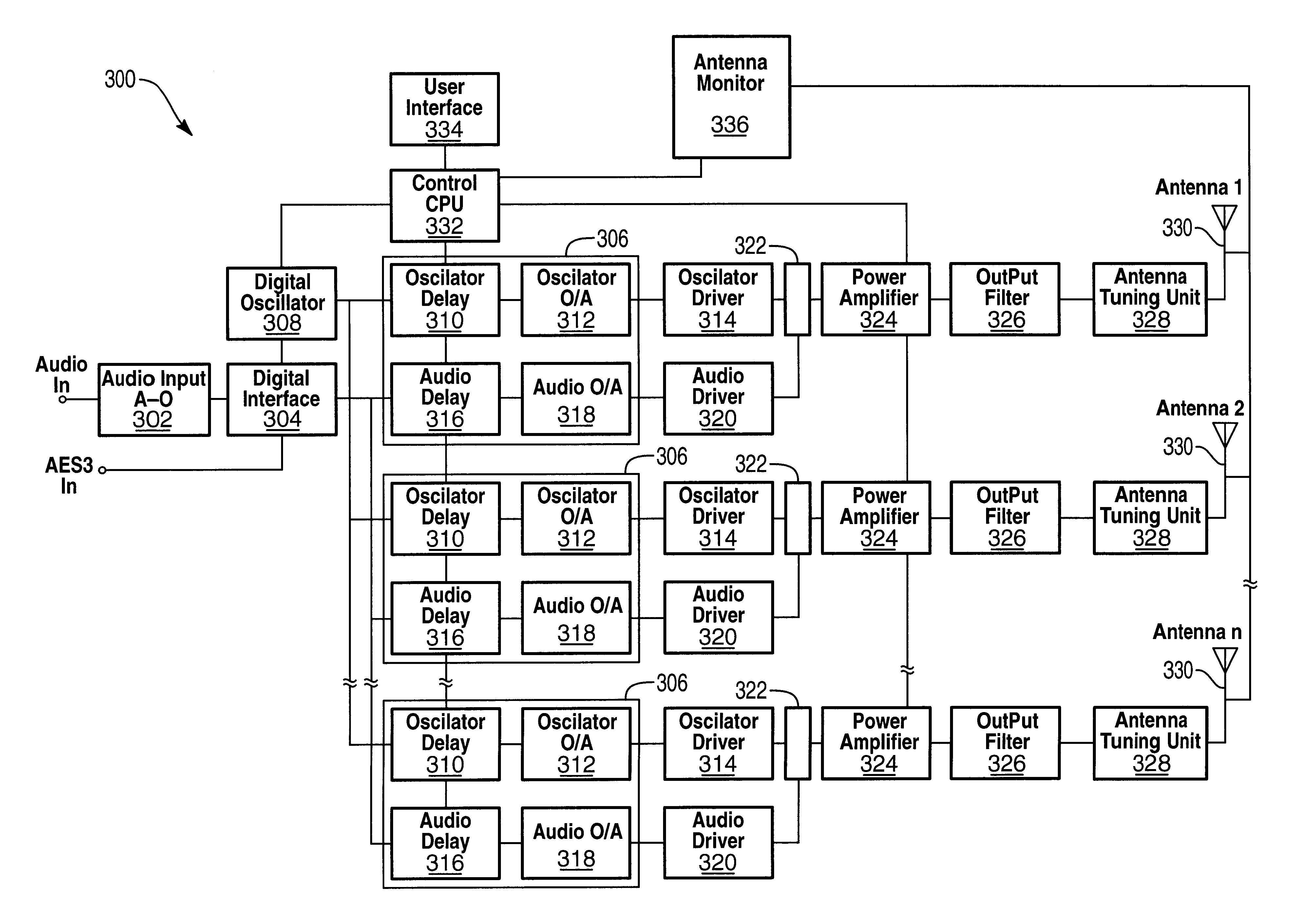
Figure 1 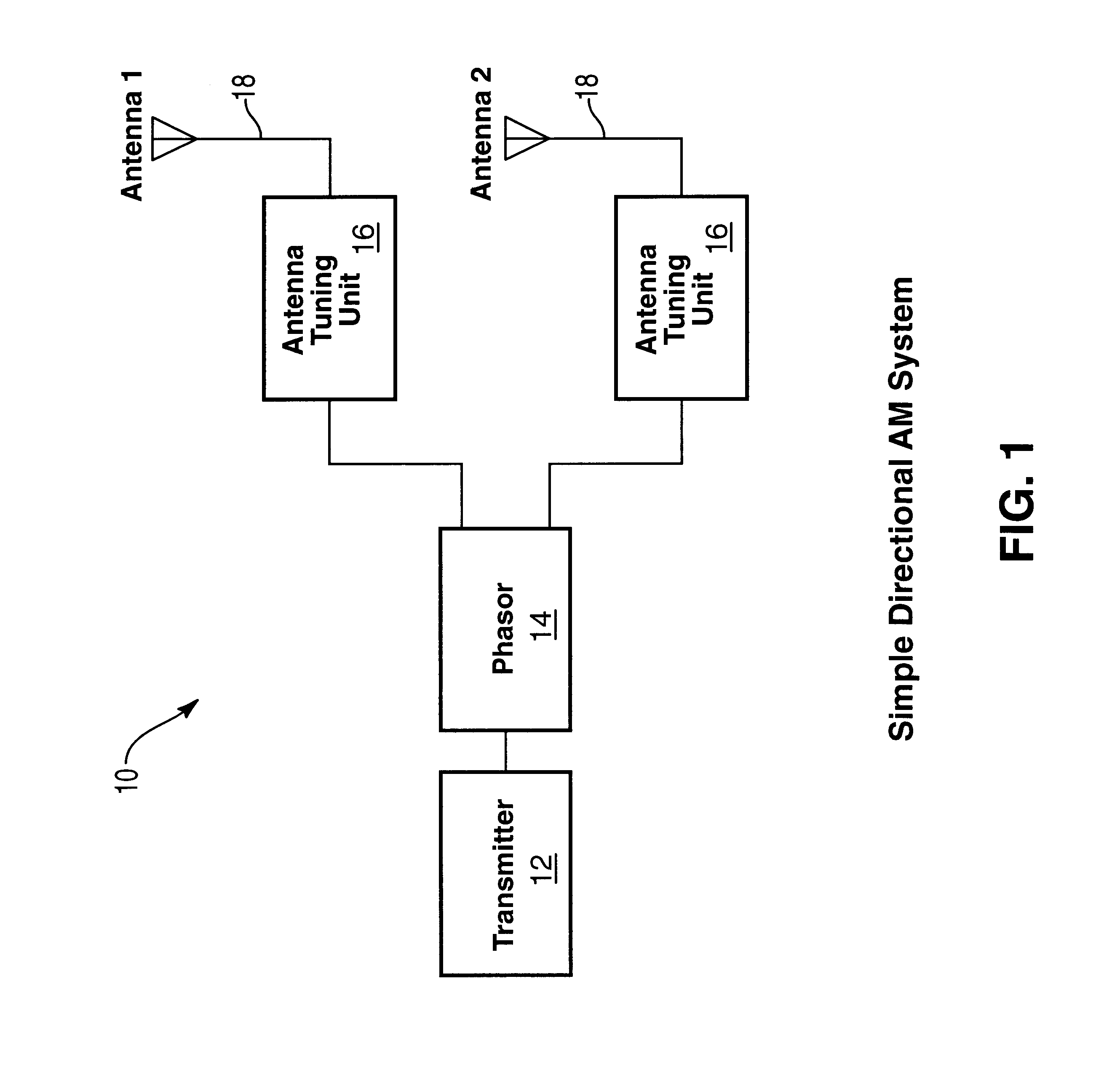
Figure 2 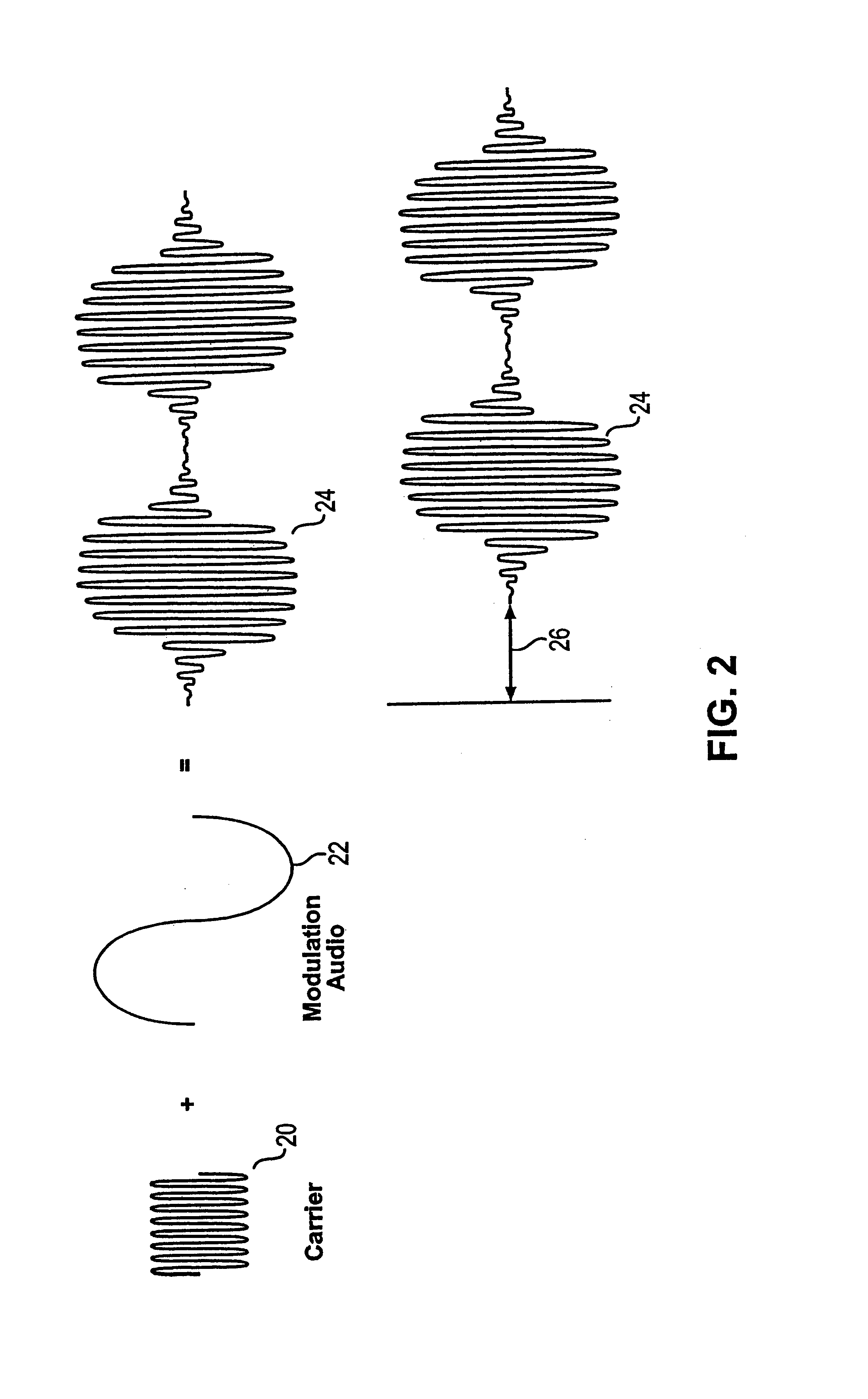
Figure 3
Abstract
Description
RELATED APPLICATIONS
[0001] The present application claims priority from U.S. patent application Ser. No. 60 / 175,071, entitled “Directional Antenna System and Digital Exciter / Phasor / Transmitter,” filed Jan. 7, 2000, which is hereby incorporated by reference.BACKGROUND OF THE INVENTION
[0002] 1. The Field of the Invention
[0003] The present invention is related to radio transmission equipment, and more specifically to directional antenna systems featuring phase shifting.
[0004] 2. Technical Background
[0005] AM and FM radio broadcasts are extremely popular for their transmission of audio programs. AM and FM radio has been employed for several decades and can be found world wide. Radio receivers have numerous embodiments including various portable receivers to be manually carried as well as being incorporated into vehicles. AM radio has a disadvantage in that it does not provide high fidelity as does FM radio. As such, AM radio has not enjoyed quite the popularity that FM radio has for musical ...
Examples
Embodiment Construction
[0025]A preferred embodiment of the invention is now described with reference to the FIGS. 1-6, where like reference numbers indicate identical or functionally similar elements. The components of the present invention, as generally described and illustrated in the Figures, may be implemented in a wide variety of configurations. Thus, the following more detailed description of the embodiments of the system and method of the present invention, as represented in the Figures, is not intended to limit the scope of the invention, as claimed, but is merely representative of presently preferred embodiments of the invention.
[0026]Present directional AM broadcast systems employ a system of power division and envelope delay to create the desired directional pattern. FIG. 1 illustrates a block diagram of a simple directional AM system 10 that may be mounted on a reference tower. The system 10 includes a transmitter 12 that may be comprised of a number of additional sub-components. The transmitt...