
Spectacle lens designing method and spectacle lens
a technology of spectacle lens and designing method, which is applied in the direction of spectacle/goggles, instruments, eye diagnostics, etc., can solve the problems of insufficient evaluation function in the optimization calculation, lack of precision in surface expression, and insufficient optical surfa
Patent Information
- Authority / Receiving Office
- US · United States
- Patent Type
- Patents(United States)
- Current Assignee / Owner
- Publication Date
- 2006-09-19
- Estimated Expiration
- Not applicable · inactive patent
Smart Images
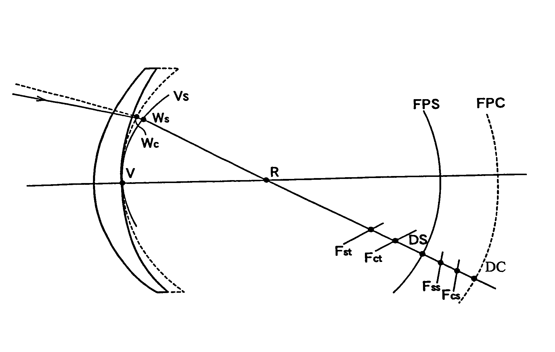
Figure 1 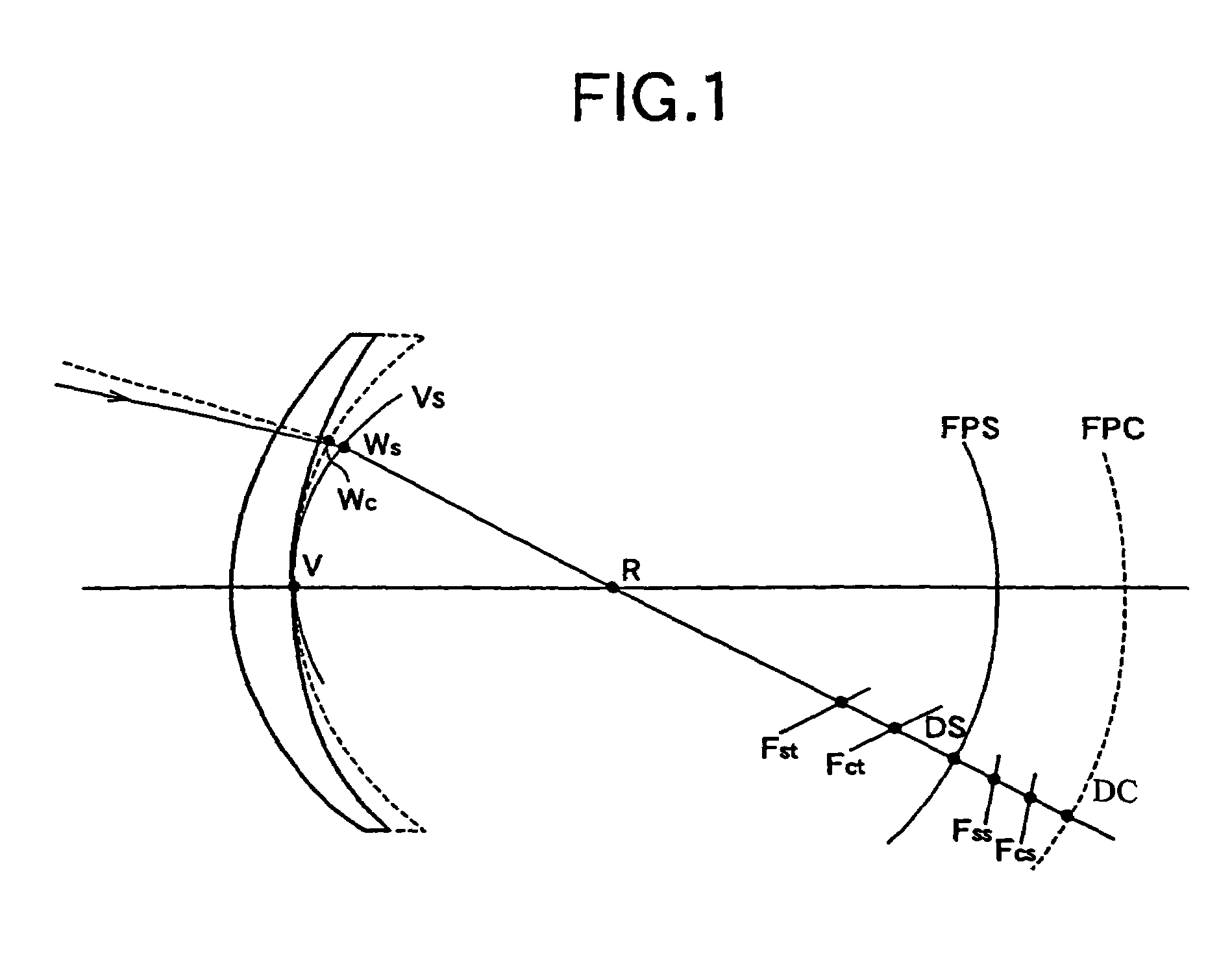
Figure 2 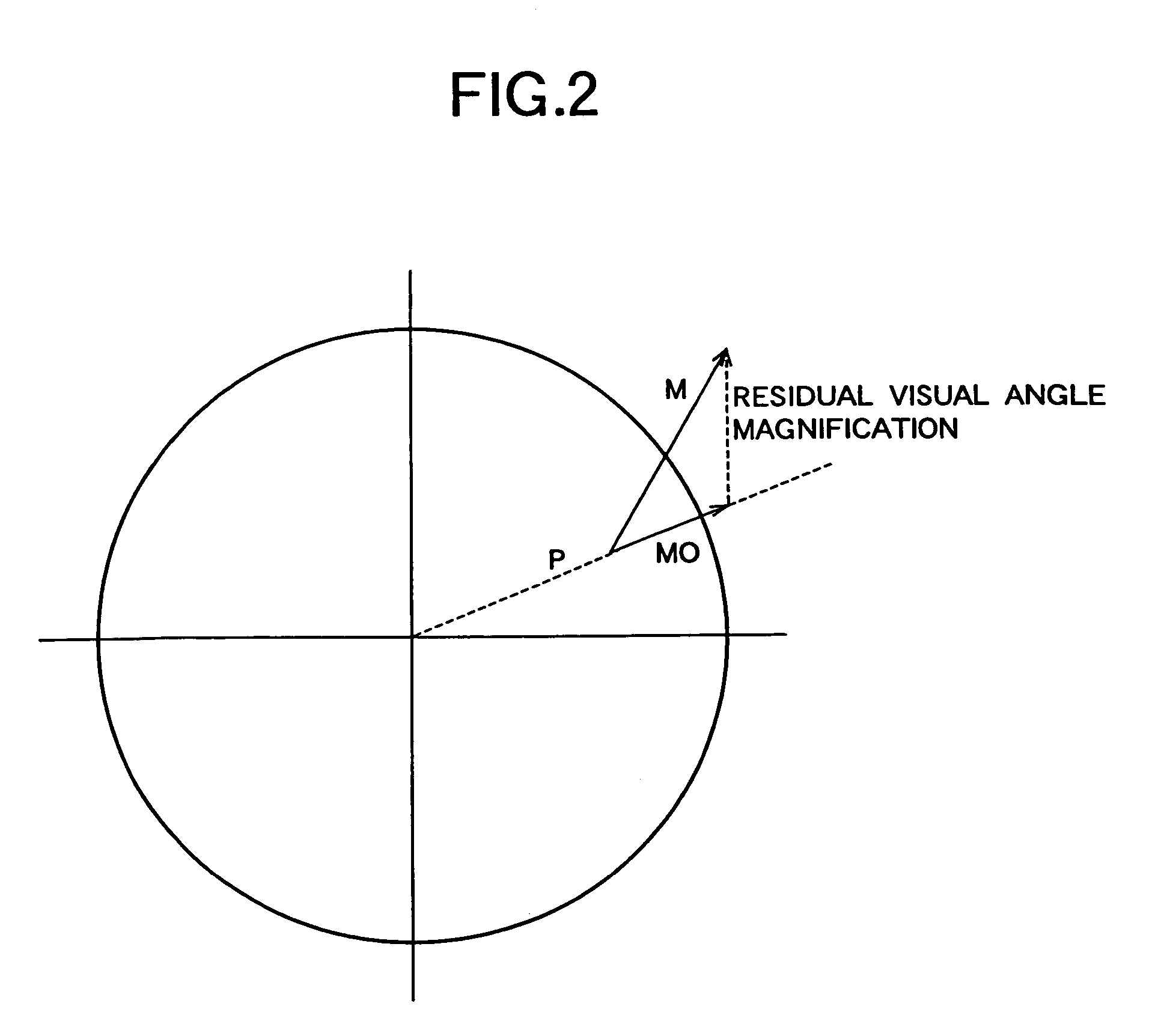
Figure 3
Abstract
Description
[0001] This is a Division of application Ser. No. 10 / 169,561 filed Jul. 26, 2002, now U.S. Pat. No. 6,811,260 which in turn is a 371 of application Ser. No. PCT / JP02 / 04244 filed Apr. 26, 2002. The entire disclosure of the prior applications is hereby incorporated by reference herein in their entireties.TECHNICAL FIELD
[0002] The present invention relates to a spectacle lens designing method and a spectacle lens designed by the same.BACKGROUND ART
[0003] The Listing's Law in an eyeball motion means that, when an eyeball looks far forward (first eye position), a rotation axis of the eyeball motion exists in a surface including the center of rotation of the eyeball and being perpendicular to this eye position (Listing's surface). In this case, when the eyeball rotates from the first eye position along spectacle principal meridians (representing two vertical and horizontal lines orthogonal to each other on a Gaussian curved surface and representing the same below) according to the Listing's ...
Examples
example 1
[0151]In Example 1, a spectacle lens is designed using the evaluation function on visual acuity of the present invention, and the outline of the designing procedure thereof will be explained below.
(Step 1): To Set a Basic Design Lens Form of Front and Rear Refractive Surfaces
[0152]In this example, a bi-aspherical lens form which has the highest degree of freedom of designing is selected, with the front surface being an aspherical surface which is axially symmetrical and expressed by the above equation (q) and with the rear surface being an aspherical surface expressed by the above equation (r).
(Step 2): To Set Fixed Conditions and Variable Conditions of a Shape Determining Factor Parameter
[0153]The design conditions are, in the prescription values, a spherical diopter is −7.00 D, a cylindrical diopter is −2.00 D, a refractive index (ne) is 1.7, a lens diameter is 75 mm, and a lens center thickness is 1 mm, as shown in FIG. 7.
[0154]In the above aspherical surface equations (q) and (r...
example 2
[0167]In Example 2, an evaluation function on the residual distortion aberration DIST is further added to Example 1 to design a spectacle lens. Since the lens does not produce visual acuity and the optimal solution cannot be obtained when only the residual distortion aberration DIST is used in the aforesaid merit function equation (p), the logMAR visual acuity value and the residual distortion aberration DIST are balanced in the equation (p).
[0168]In the equation (p), a=1, b=0, c=0.02, u=1, and w=1, and the equation (j) is used for the equation for the visual acuity evaluation function logMAR.
[0169]The equations (q), (r) are used for the bi-aspherical surface equation, k(θ) is 0, and the equation (t) is applied for a(n, θ).
[0170]The data in FIG. 5 in Example 1 are used for the front surface. Though this is not a suitable condition for greatly improving the residual distortion aberration DIST since a fixed condition is set for the front and rear surfaces the optimization calculation ...