
Electrical signal transmission connector assembly with magnetically connected receptacle and plug
a technology of electrical signals and connectors, which is applied in the direction of telephony connectors, electrical devices, coupling device connections, etc., can solve the problems of increasing the weight of cables, and affecting the service life of cables
Patent Information
- Authority / Receiving Office
- US · United States
- Current Assignee / Owner
- Publication Date
- 2008-03-11
- Estimated Expiration
- Not applicable · inactive patent
Smart Images
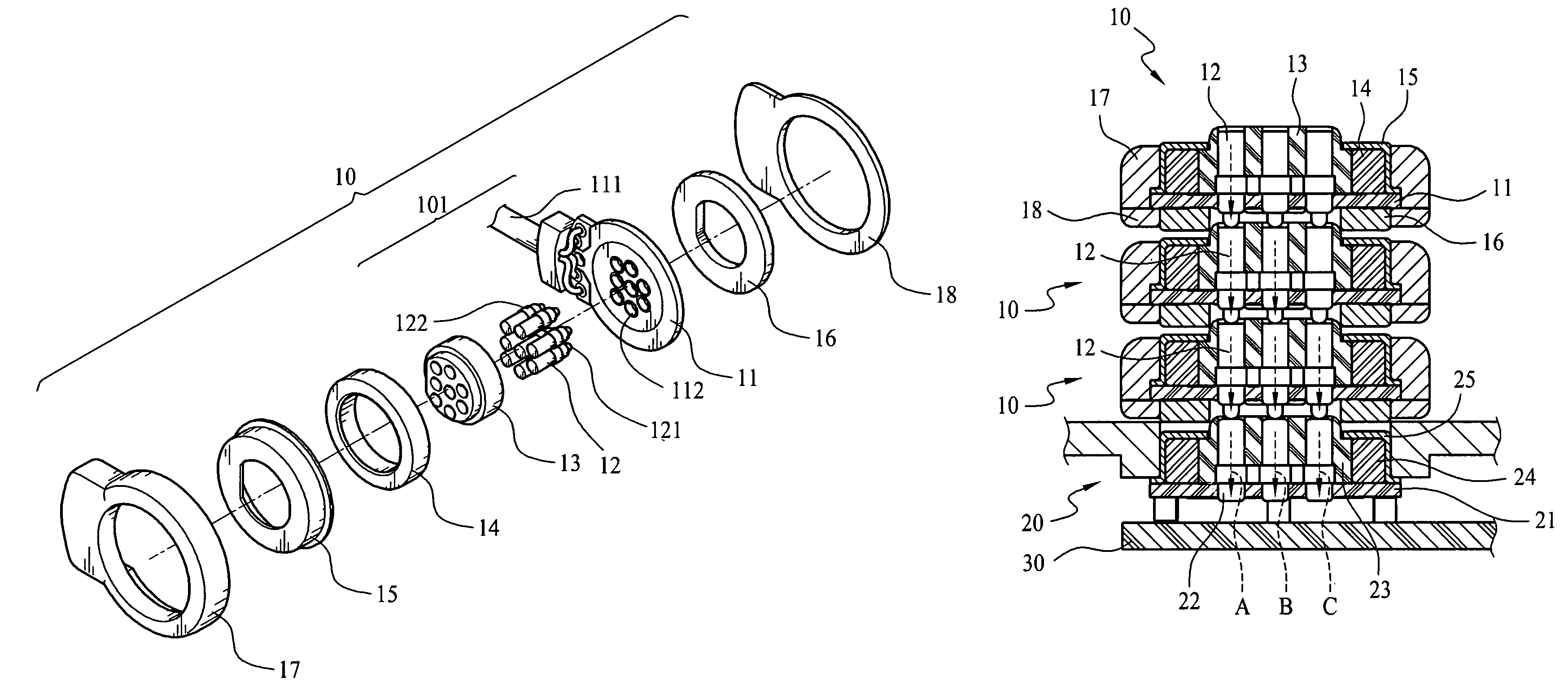
Figure 1 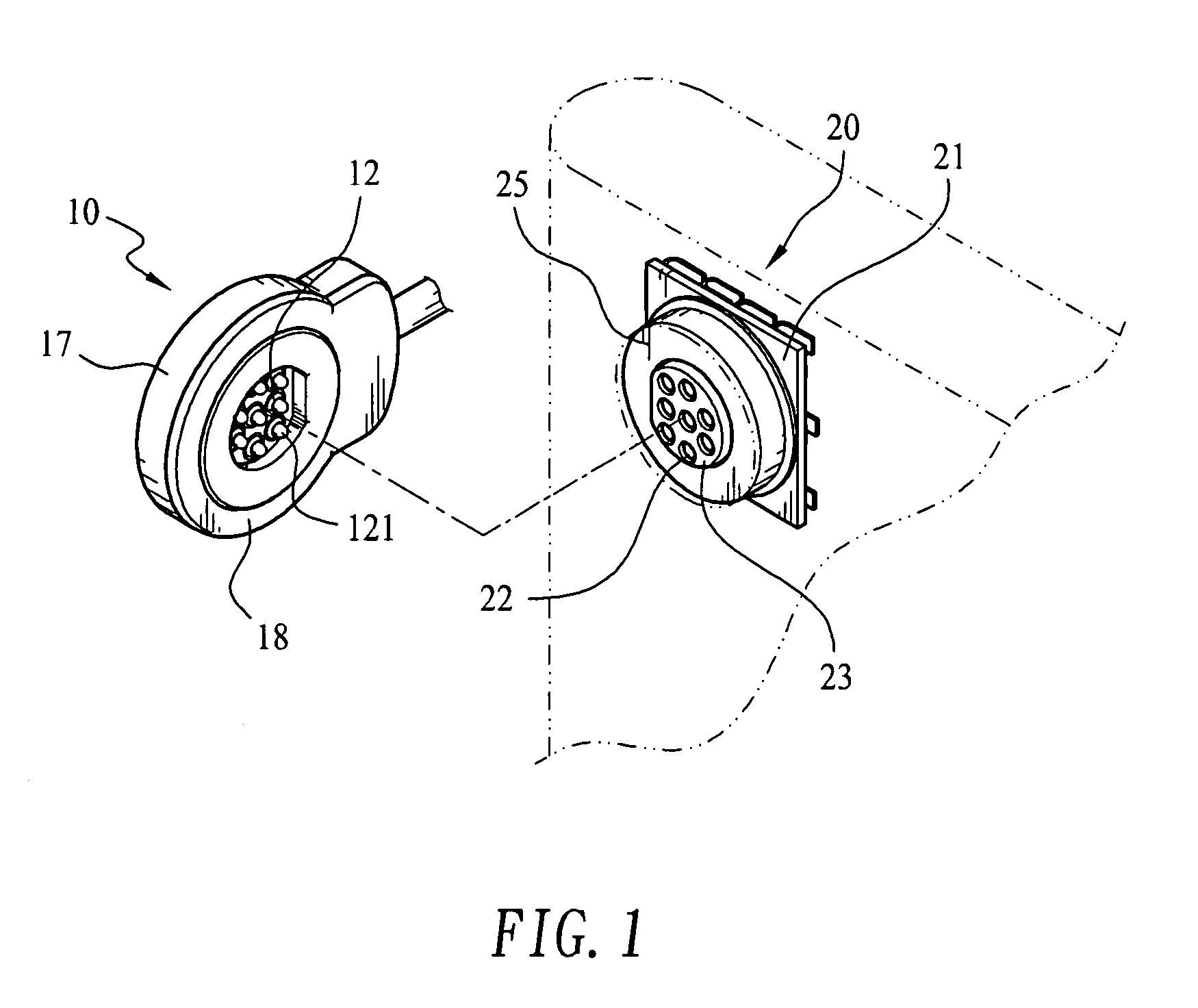
Figure 2 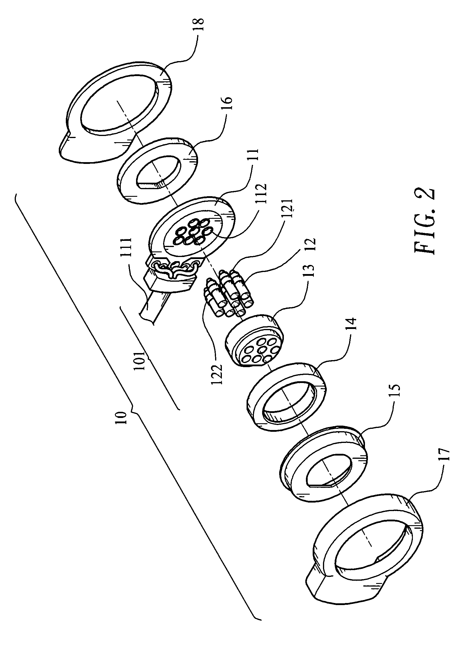
Figure 3
Abstract
Description
FIELD OF THE INVENTION
[0001] The present invention relates to an electric signal transmission connector assembly, and more particularly to a connector assembly including a receptacle and at least one stackable plug, which are internally provided with a magnet each, so as to magnetically connect to one another.BACKGROUND OF THE INVENTION
[0002] With the advanced technologies, there are developed more and more types of electronic products, which are able to integrate multiple different functions. For this purpose, there are multiple electric connector assemblies provided on the modern electronic products for connecting to other electronic product for transferring data between them.
[0003] A connector assembly on general electronic products, such as earphones, USB devices, power supply, etc., usually includes a male connector or plug that has a projected blade as long as 1 cm to 2 cm for plugging in a female connector or receptacle. The projected blade is held to the receptacle by frictiona...
Examples
Embodiment Construction
[0033]Please refer to FIG. 1 that is a perspective view of a connector assembly according to an embodiment of the present invention. As shown, the connector assembly of FIG. 1 includes a plug 10 and a receptacle 20 that are magnetically connected to each other for transmitting electric signals. Please also refer to FIGS. 2 and 3 that are exploded perspective views of the plug 10 and the receptacle 20, respectively. As can be seen from FIGS. 2 and 3, the plug 10 and the receptacle 20 internally include a permanent magnet 14 and 24, respectively, so that the plug 10 can be magnetically connected to the receptacle 20 to enable transmission of electric signals and supply of power via the connector assembly of the present invention.
[0034]FIG. 4 is a sectioned side view showing the plug 10 and the receptacle 20 before being magnetically connected to each other. Please refer to FIGS. 2 and 4 at the same time. The plug 10 includes an upper and a lower case 17, 18 that together define an int...