
Connector
a technology of connecting rods and connectors, applied in the direction of coupling device connections, connection contact member materials, coupling protective earth/shielding arrangements, etc., can solve the problems of connectors suffering from the problem of an increase in size, crosstalk between the pair of signal contacts, etc., to prevent the degradation of transmission
Patent Information
- Authority / Receiving Office
- US · United States
- Patent Type
- Patents(United States)
- Current Assignee / Owner
- Publication Date
- 2010-09-21
- Estimated Expiration
- Not applicable · inactive patent
Smart Images
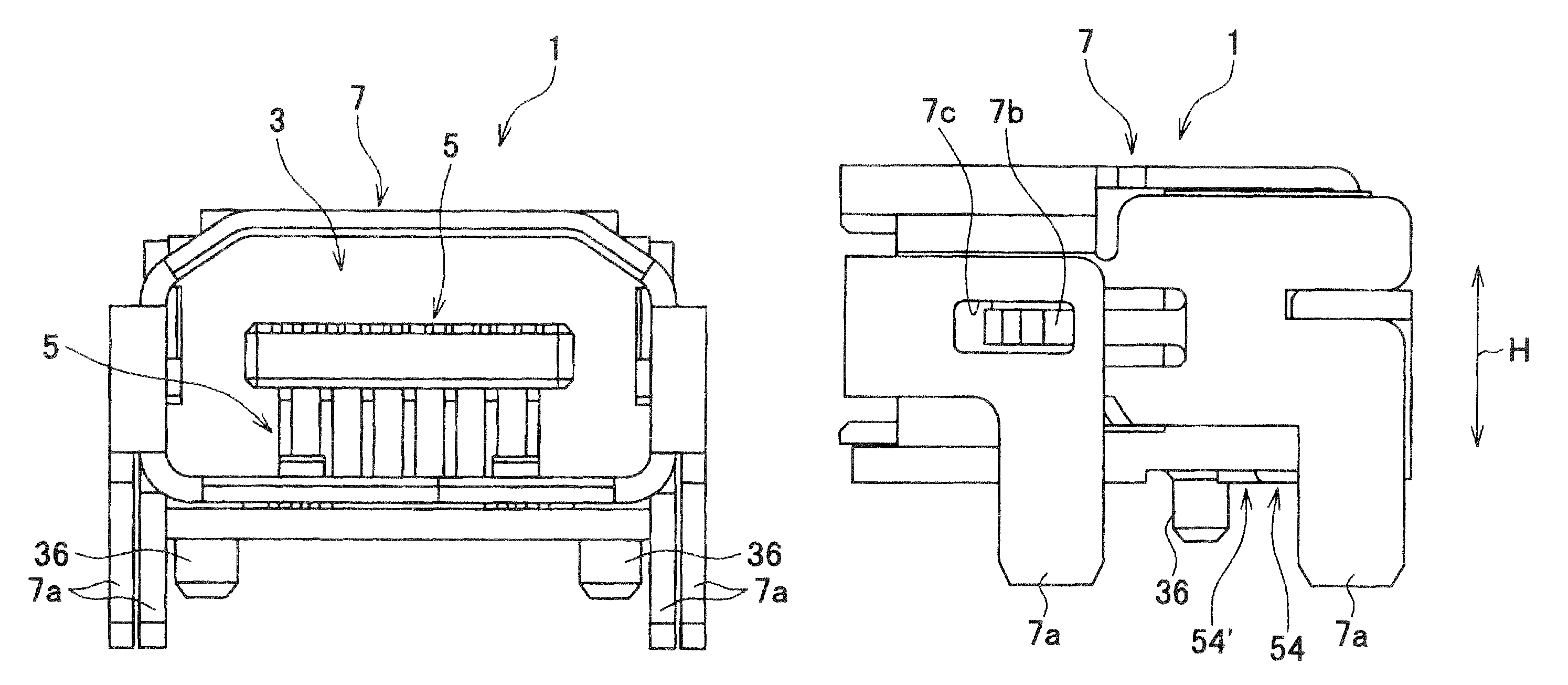
Figure 1 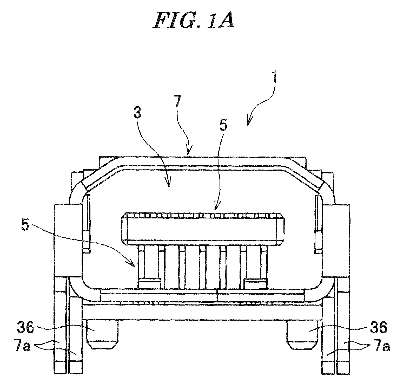
Figure 2 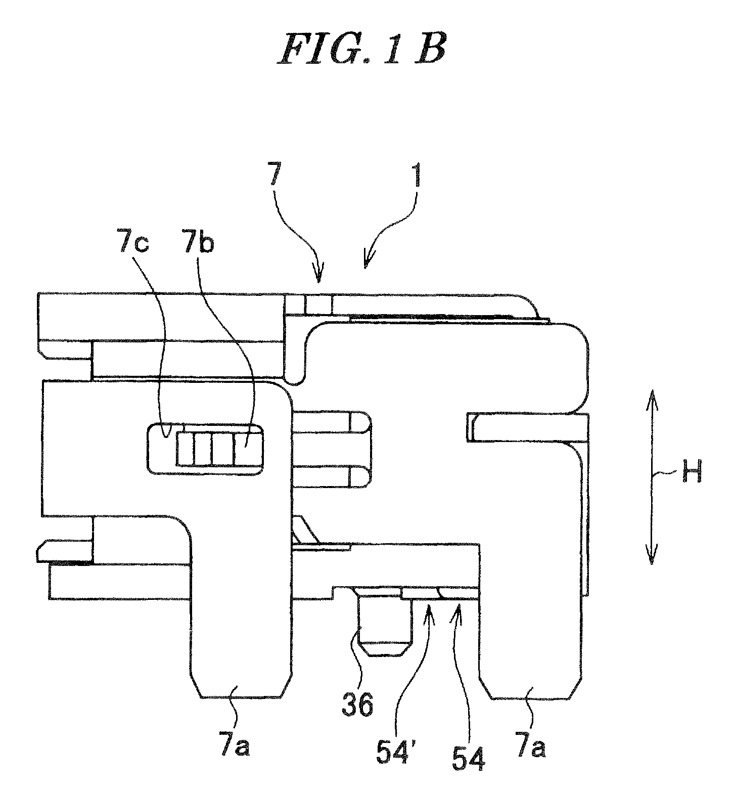
Figure 3
Abstract
Description
BACKGROUND OF THE INVENTION
[0001] 1. Field of the Invention
[0002] This invention relates to a connector, more particularly to a connector which is suitable for high-speed transmission of electric signals.
[0003] 2. Description of the Related Art
[0004] Conventionally, there has been proposed a receptacle connector comprised of three types of contacts, an insulator for holding the contacts, and a receptacle shell for covering the insulator (see Japanese Laid-Open Patent Publication (Kokai) No. 2002-334748).
[0005] The three types of contacts include a signal contact S and a ground contact G for high-speed transmission, and a contact D for non-high-speed transmission. Each of the three types of contacts has contact portions which are capable of being brought into contact with contact portions of mating contacts of a mating connector, and terminal portions which are capable of being soldered to pads on a printed board.
[0006] The contact portions are arranged in two rows, one above the other (se...
Examples
second embodiment
[0051]FIG. 5A is a front view of a connector according to the present invention, and FIG. 5B is a side view of the connector. FIG. 6 is a cross-sectional view of part of the connector shown in FIG. 5A.
first embodiment
[0052]The connector 201 is the mating connector of the connector 1 according to the
[0053]Although in the connector 1, each of the first and second signal contacts 51 and 52, the ground contacts 53, and the contacts 54 and 54′ for non-high speed transmission is bent into L-shape, in the connector 201, each of first and second signal contacts 251 and 252, ground contacts 253, and contacts 254 and 254′ for non-high speed transmission has a linear shape.
[0054]Although in the connector 1, each of the terminal portions (connection portion) 51d, 52d, 53d, 54d, and 54d′ of the respective contacts 51, 52, 53, 54, and 54′ has a shape for being mounted on the printed board, in the connector 201, each of wiring portions (terminal portions), not shown, of respective contacts 251, 252, 253, 254, and 254′ has a shape which is capable of being connected to cables.
[0055]Although in the connector 1, the terminal portions 54d and 54′d of the contacts 54 and 54′ for non-high-speed transmission are in s...