
Clamp assembly for a steering column assembly
a technology for steering column and clamp assembly, which is applied in the direction of snap fasteners, buckles, transportation and packaging, etc., can solve the problems of teeth or locking mechanism damag
Patent Information
- Authority / Receiving Office
- US · United States
- Patent Type
- Patents(United States)
- Current Assignee / Owner
- Publication Date
- 2013-04-09
- Estimated Expiration
- Not applicable · inactive patent
Smart Images
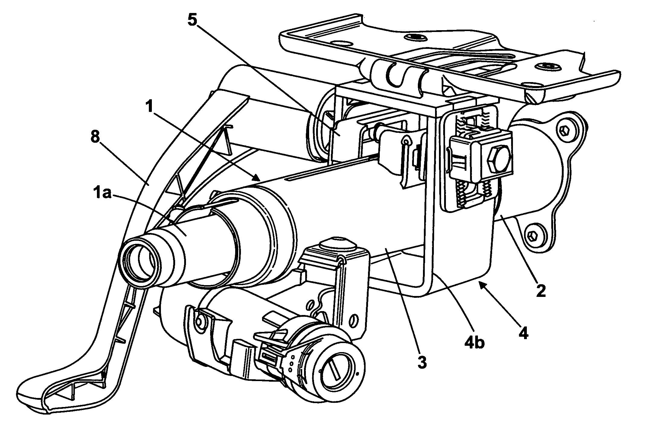
Figure 1 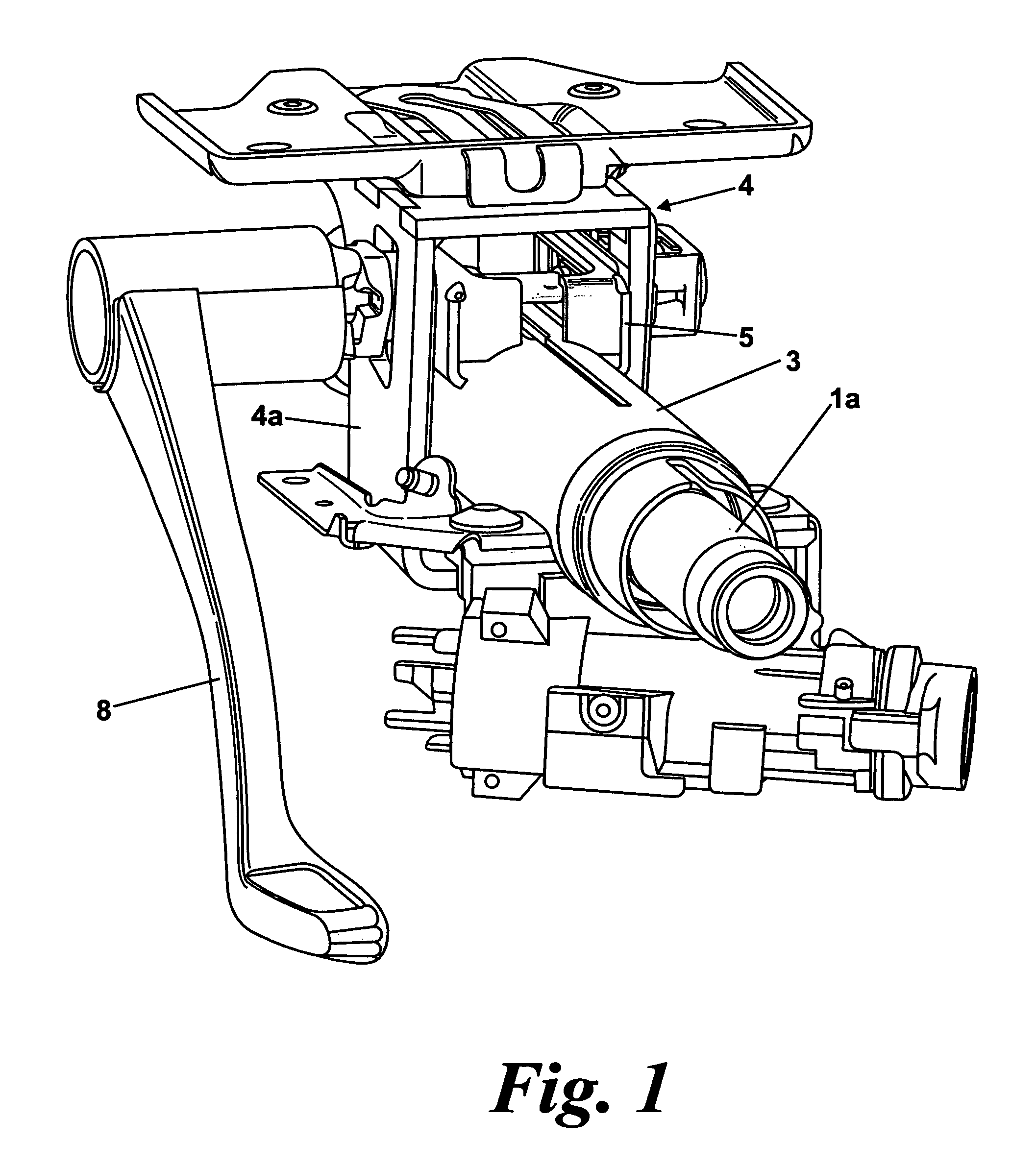
Figure 2 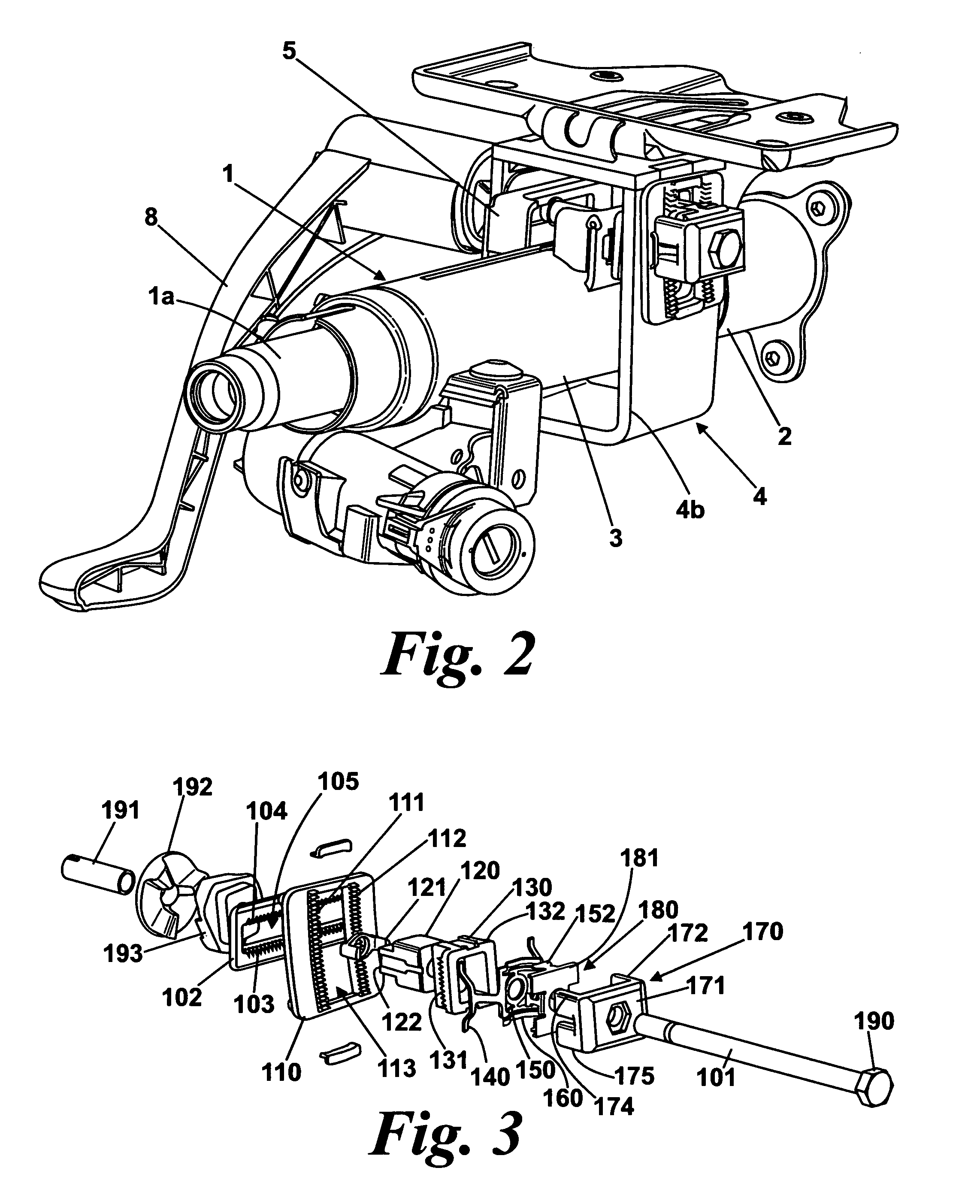
Figure 3
Abstract
Description
CROSS-REFERENCE TO RELATED APPLICATIONS
[0001] This application is a national stage of International Application No. PCT / GB2008 / 003431 filed Oct. 10, 2008, the disclosures of which are incorporated herein by reference in entirety, and which claimed priority to Great Britain Patent Application No. 0719971.4 filed Oct. 12, 2007, the disclosures of which are incorporated herein by reference in entirety.BACKGROUND OF THE INVENTION
[0002] This invention relates to improvements in clamp assemblies for steering column assemblies, especially but not exclusively to electric power assisted steering assemblies. In particular it relates to clamp assemblies for steering column assemblies adjusted for both rake and reach.
[0003] It is known to provide a steering column assembly in which a steering wheel is connected to one or more road wheels through a collapsible or telescopic steering column shaft. The shaft is designed to collapse away from a driver of the vehicle if a load is applied to the steerin...
Examples
Embodiment Construction
[0049]An embodiment of a steering column assembly for a vehicle which incorporates a clamp assembly according to a first aspect of the invention is shown in FIGS. 1 and 2 of the accompanying drawings. It comprises a telescopic steering column shroud having an upper portion 3 and a lower portion 2 that fits around a telescopic steering shaft (1a as shown in FIGS. 1 and 2). The upper portion 3, referred to herein as a moving portion, can slide up and down the lower portion to enable the length of the shroud to be adjusted.
[0050]The movement of the moving portion 3 is achieved by supporting it within two downwardly extending arms 4a, 4b of a support bracket 4. The bracket 4 will be referred to herein after as the fixed portion, being considered fixed in that it is fixed relative to the vehicle body (not shown). The moving portion 3 is reinforced by a box section rail 5 welded to it to prevent it collapsing and this box section 2 fits snugly between the two arms 4a,4b of the bracket 4.
[...