
Adjustable spanner
a technology of adjustable spanners and adjustable bars, which is applied in the direction of wrenches, screwdrivers, manufacturing tools, etc., can solve the problems of restricting the movement of the fastening device, and achieve the effect of quick turning of objects and satisfactory structural strength
Patent Information
- Authority / Receiving Office
- US · United States
- Patent Type
- Patents(United States)
- Current Assignee / Owner
- Publication Date
- 2015-11-24
Smart Images
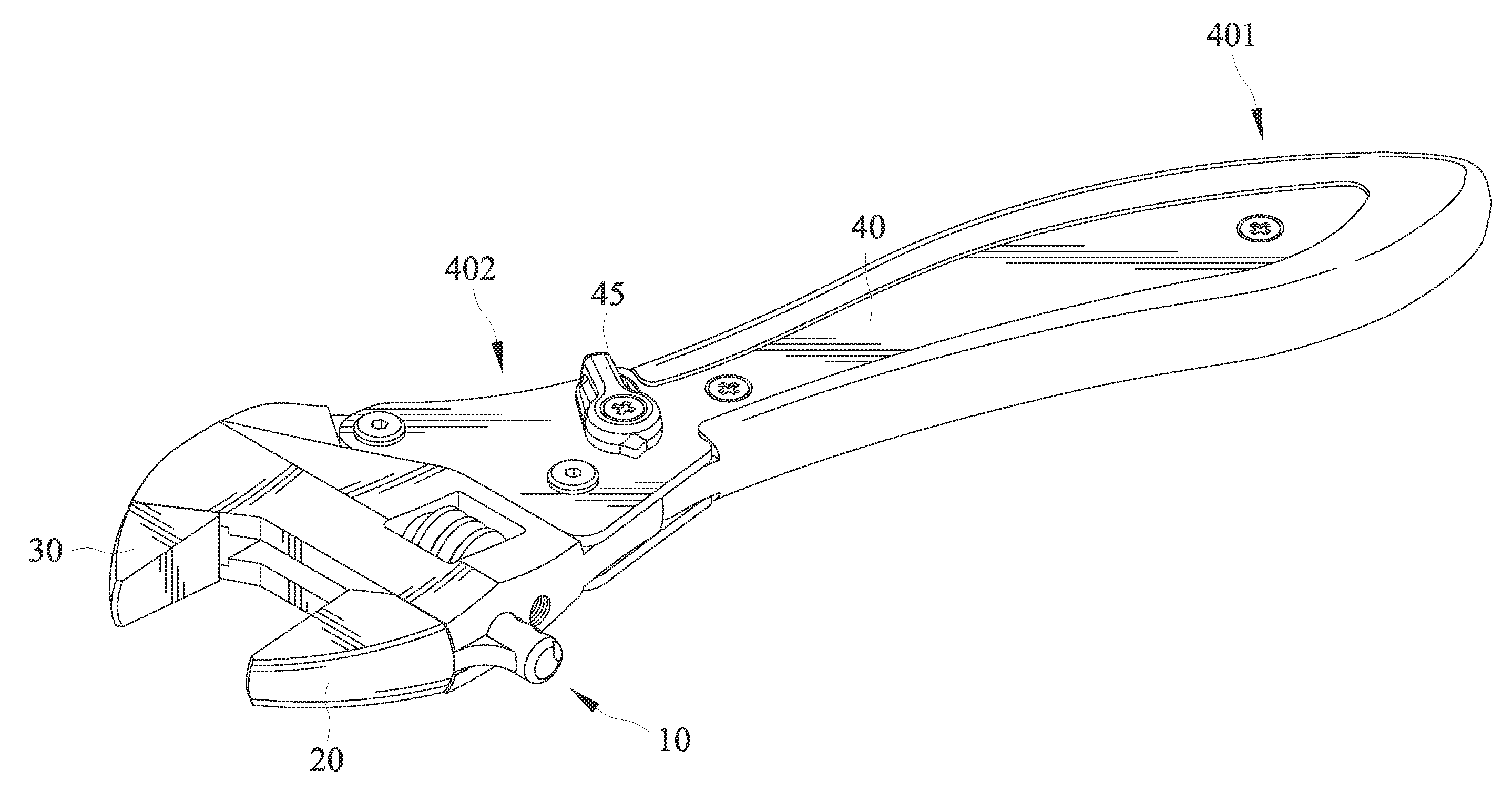
Figure 1 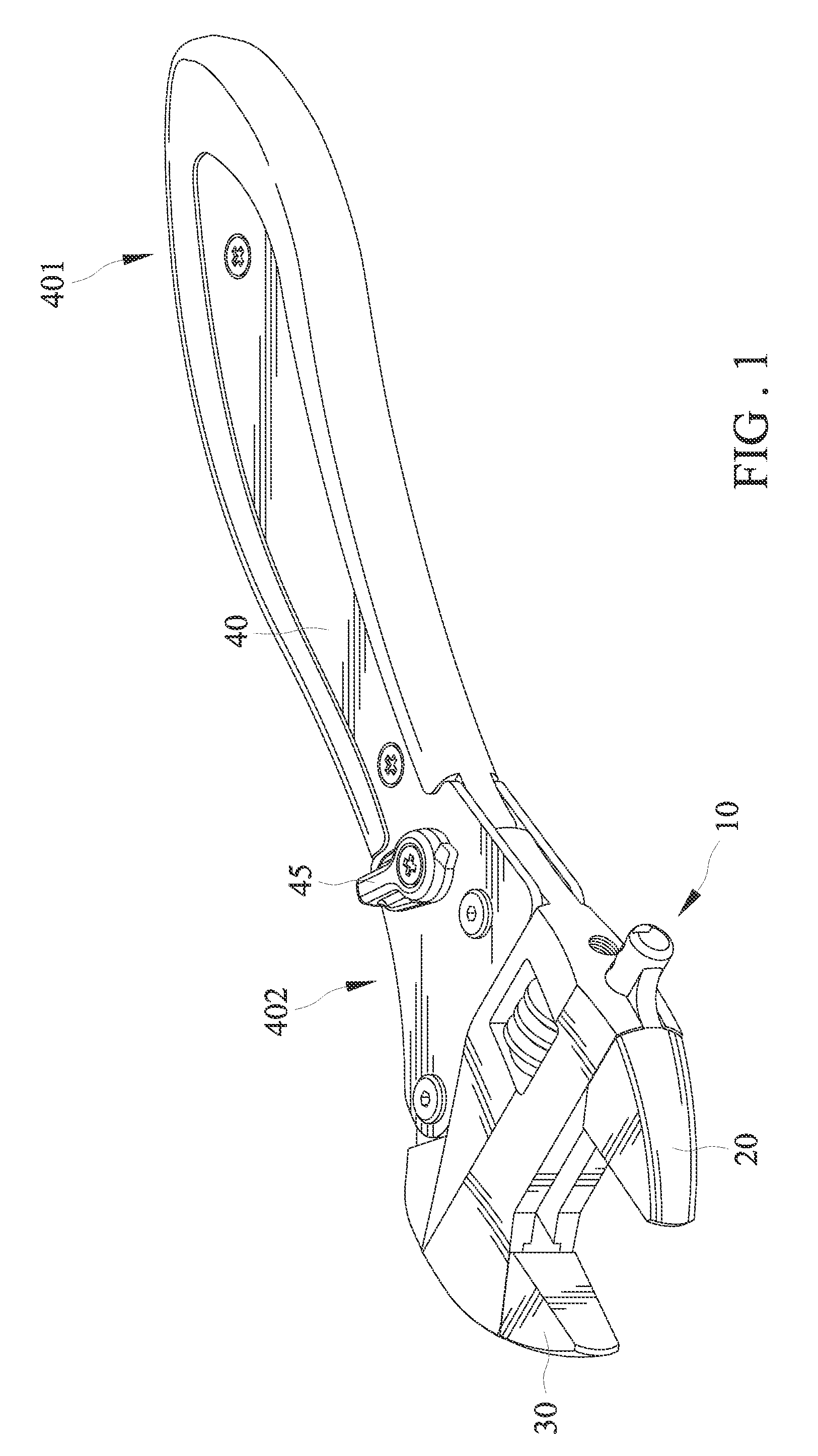
Figure 2 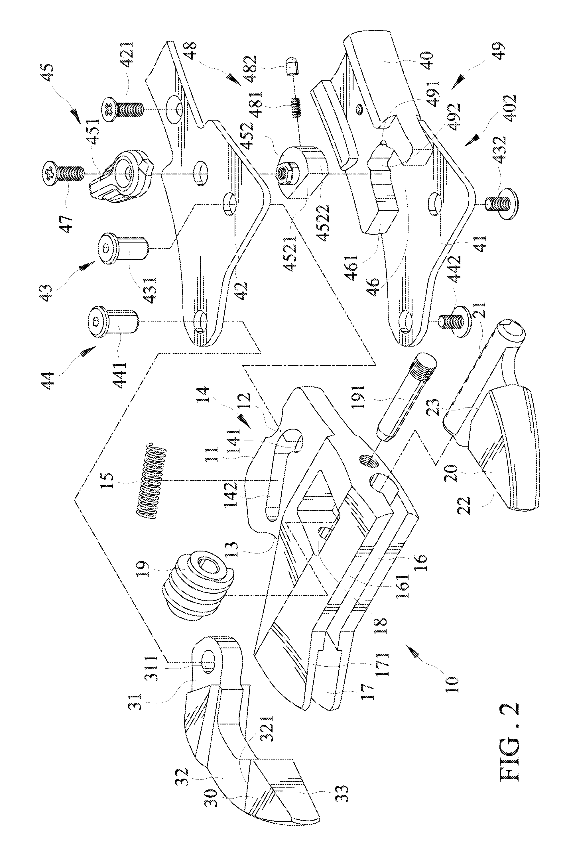
Figure 3
Abstract
Description
BACKGROUND
[0001] 1. Field of the Invention
[0002] The present invention relates to an adjustable spanner, and particularly, to an adjustable spanner for quickly turning an object.
[0003] 2. Description of the Related Art
[0004] U.S. Pat. No. 6,336,384 shows an adjustable wrench for quickly turning an object. The adjustable wrench includes a main body, a slide block, a movable jaw and a grip. The main body includes a jaw section and a hollow section in which the slide block and the movable jaw are disposed. The grip is pivotally connected with the hollow section. A movable retaining block is disposed on one side of the top end of the grip and is opposite to a leaning section of the slide block. The retaining block can be switched, whereby when the grip is wrenched in different directions, the retaining block pushes the leaning section of the slide block so as to change the one-way wrenching direction of the adjustable wrench during repeated wrenching operation for an object. However, since ...
Examples
Embodiment Construction
[0029]Referring to FIGS. 1 through 12, an adjustable spanner for quickly turning an object in accordance with a first embodiment of the present invention includes a moving member 10, a first jaw 20, a second jaw 30, and a grip 40.
[0030]The moving member 10 is movably joined to the grip 40 and comprises an end edge 11, a recess 12, a cavity 13, an elastic member 15, first and second guiding channels 16 and 17, a room 18, and a worm gear 19. The end edge 11 is defined on the outer periphery of the moving member 10 and extends in a length and provides a contact with the grip 40 when the adjustable spanner is in operation for turning an object “A”. The contact between the end edge 11 and the grip 40 allows the adjustable spanner to withstand a relatively large torque force imparted thereto. The end edge 11 and the grip 40 are in line contact with each other. The recess 12 is defined on an end edge 11. Likewise, the recess 12 is defined on the outer periphery of the moving member 10. The...