
Auxiliary medical appliance for mouth supporting
A technology for medical aids and appliances, applied in the field of medical aids, can solve the problems of inconvenient adjustment of the height of the support, poor practicability, waste of manpower, etc., and achieves the effects of hygienic operation, ingenious design, scientific and reasonable, and easy to use.
Patent Information
- Authority / Receiving Office
- CN · China
- Patent Type
- Applications(China)
- Current Assignee / Owner
- Publication Date
- 2016-05-11
- Estimated Expiration
- Not applicable · inactive patent
Smart Images
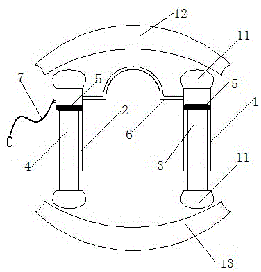
Figure 1 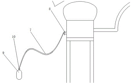
Figure 2
Abstract
Description
technical field
[0001] The invention relates to an oral medical aid, in particular to a medical aid for oral support, and belongs to the technical field of medical aids. Background technique
[0002] The oral cavity is the beginning part of the digestive canal. The anterior cleft communicates with the outside world, and the posterior pharynx connects with the pharynx. There are teeth, tongue and other organs in the oral cavity. The front wall of the oral cavity is the lips, the side wall is the cheek, the top is the palate, The floor of the mouth is composed of mucous membranes and muscles.
[0003] Oral support frame is a common tool used in oral surgery. Generally, comatose patients, anesthetized patients and even patients with uncontrollable nerves will bite their tongues, and some attempt suicide. When treating patients, they will also bite their own tongues. Bite the doctor's finger, so a brace needs to be placed in the patient's mouth to separate the upper and lower t...
Examples
Embodiment Construction
[0013] A medical aid for oral cavity support will be further described below in conjunction with the accompanying drawings.
[0014] Such as figure 1 and figure 2 As shown, a medical aid for oral support, the structure includes: right support cylinder 1, left support cylinder 2, right support column 3, left support column 4, piston 5, trachea 6, inflatable tube 7, inflatable nozzle 8 , inflatable bag 9, deflation valve 10, described right support 3 columns are installed in the right support cylinder 1, left support column 4 is installed in the left support cylinder 2, described left support column 4 and right support column 3 are installed The piston 5, the left support cylinder 2 and the right support cylinder 1 are communicated through the air pipe 6, the left support cylinder 2 is provided with an inflation nozzle 8, one end of the inflation pipe 7 is connected to the inflation nozzle 8, and the other end is connected to the air release valve 10, Described deflation valv...