

Ultrasonic medical coupling agent automatic applicator
A couplant and medical technology, applied in the field of ultrasound medicine, can solve the problems of insufficient automation, single application method, and inability to fit the skin surface well, and achieve the effect of high degree of automation and high work efficiency
Patent Information
- Authority / Receiving Office
- CN · China
- Patent Type
- Applications(China)
- Current Assignee / Owner
- Publication Date
- 2019-07-16
- Estimated Expiration
- Not applicable · inactive patent
Smart Images
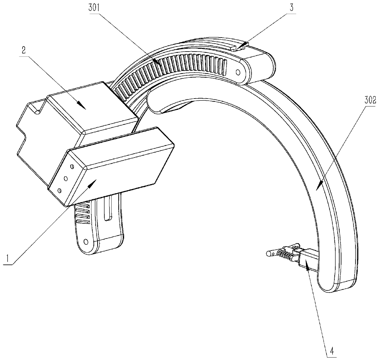
Figure 1 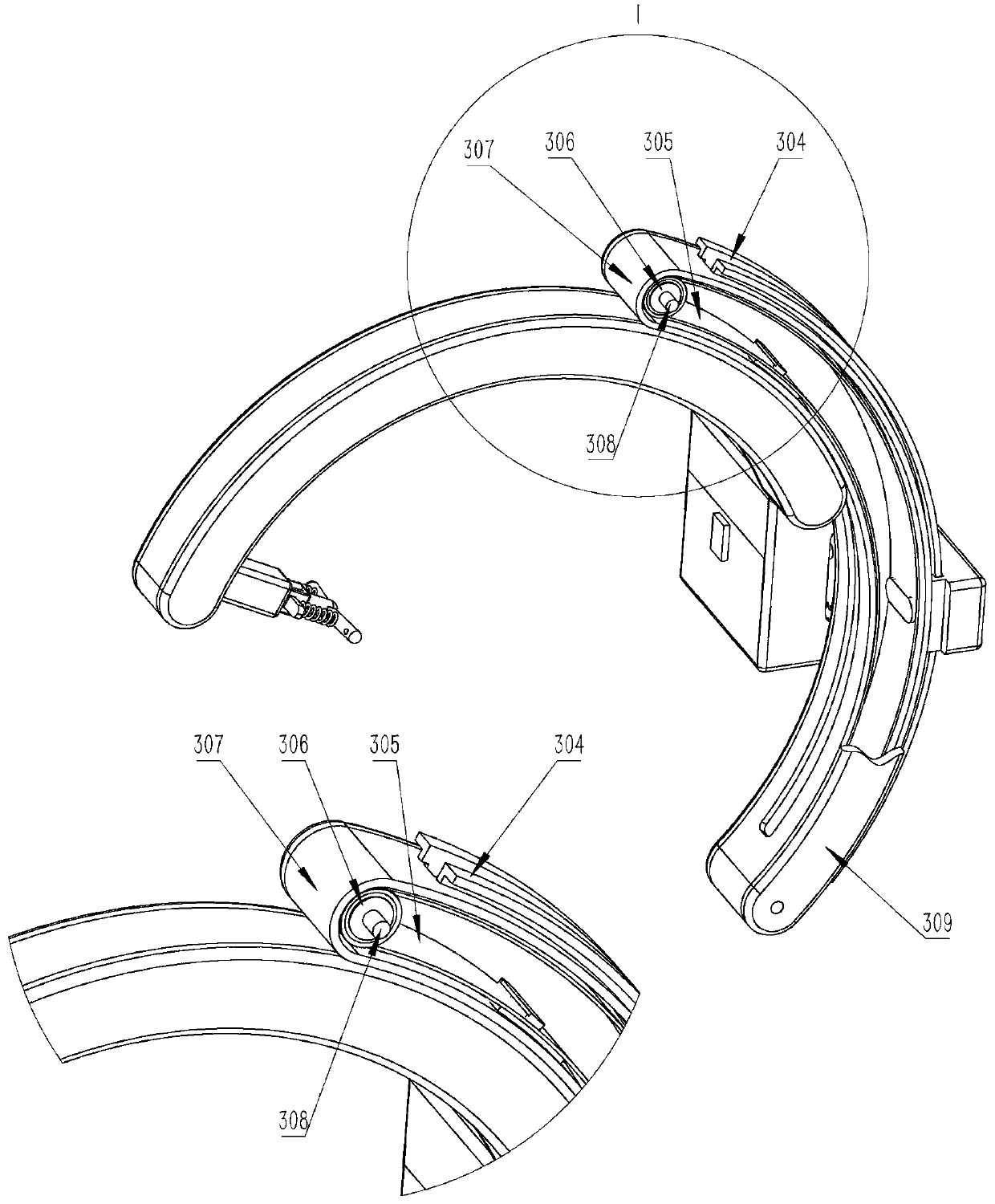
Figure 2 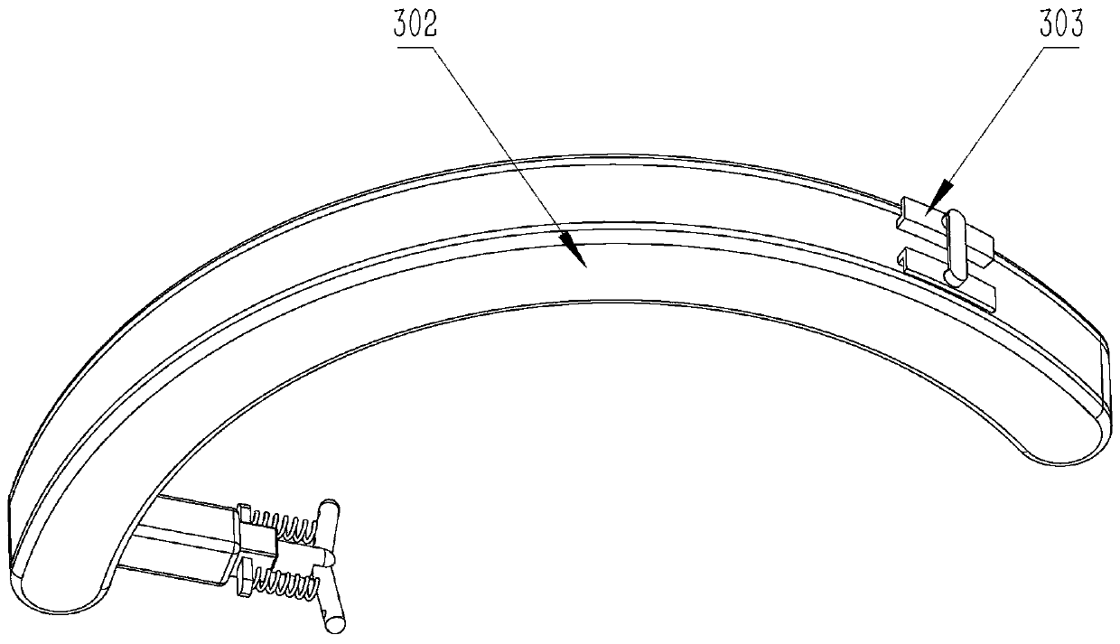
Figure 3
Abstract
Description
technical field
[0001] The invention relates to the technical field of ultrasonic medicine, in particular to an automatic smearing instrument for ultrasonic medical coupling agent. Background technique
[0002] The development of ultrasound medicine in today's medical field has made the application of ultrasound medicine more and more extensive in clinical practice. Before an ultrasound examination, a gel must be applied to the skin surface in contact with the ultrasound probe. However, manual application is time-consuming and laborious each time, so an automatic application device is needed to improve work efficiency. Also by some equipment, such as a kind of couplant applicator of [CN 207591099U], this device is only a kind of tool for smearing, still needs manual operation, can't really improve efficiency; Another example is the ultrasonic inspection of [CN 207755296 U] As for the couplant applicator, the smearing surface of the device is flat, and the smearing method i...
Examples
Embodiment
[0019] Example: such as figure 1 , figure 2 , image 3 , Figure 4 , Figure 5 , Figure 6 An ultrasonic medical gel automatic applicator is shown.
[0020] Such as Figure 4 Shown is a specific structural schematic diagram of the lateral movement mechanism 1 in the present invention, the screw rod 101 is connected to the screw rod base 106 and can rotate freely, the first motor 109 is fixed to the screw rod base 106, and is fixed to the shaft coupling 108, Coupling 108 is fixed with one end of screw mandrel 101, and nut 102 moves on screw mandrel 101, and nut holder 103 is fixed with nut 102, and is fixed with gear seat 206, changes screw mandrel 101 strokes according to the needs of smearing range.
[0021] Such as Figure 5 Shown is the specific structural diagram of the arc motion drive mechanism 2 in the present invention, the second motor 207 is fixed in the gear seat 206; the motor gear 208 is fixed with the second motor 207; the idler gear 201 meshes with the m...