
Soil infiltration capacity monitoring device and monitoring method
A monitoring device and soil technology, applied in measurement devices, permeability/surface area analysis, suspension and porous material analysis, etc., can solve the problems of high monitoring cost, extremely high instrument requirements, affecting the accuracy of monitoring results, and reduce labor Strength, the effect of improving accuracy
Patent Information
- Authority / Receiving Office
- CN · China
- Patent Type
- Applications(China)
- Current Assignee / Owner
- Publication Date
- 2020-08-25
Smart Images
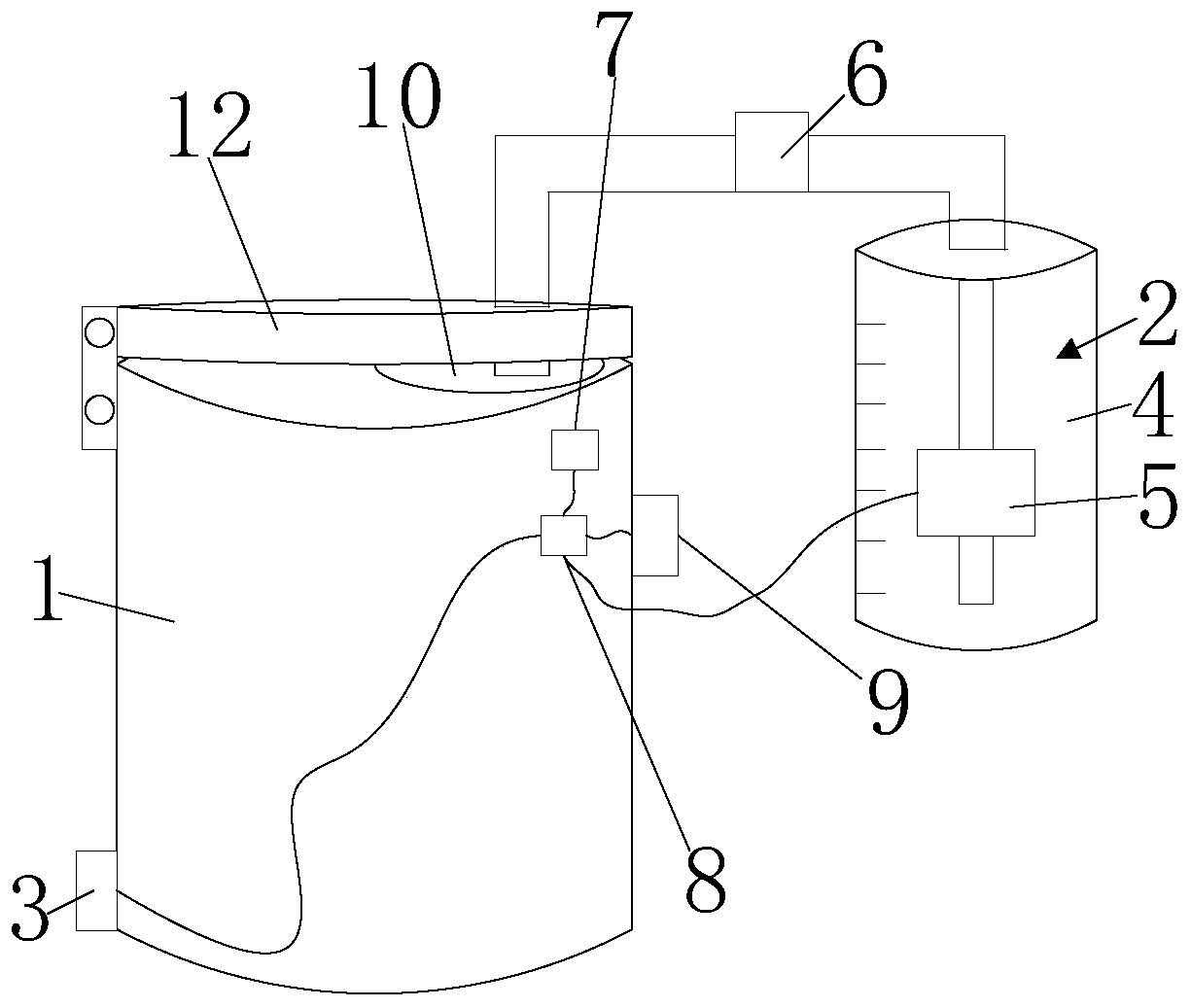
Figure 1 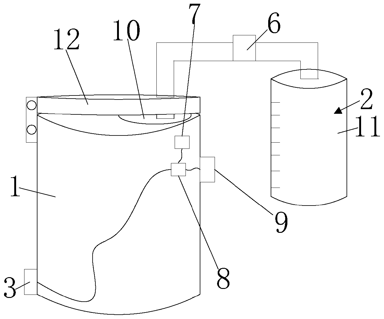
Figure 2 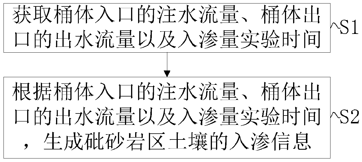
Figure 3
Abstract
Description
technical field
[0001] The invention relates to the technical field of natural monitoring experimental equipment, in particular to a soil infiltration capacity monitoring device and a monitoring method. Background technique
[0002] The arsenic sandstone is known as the cancer of the earth. It turns into mud when it meets water, and its soil aggregation ability is poor. Moreover, the annual rainfall in the sandstone area is low, and most of the rainfall is heavy rain. After the rain, most of the water is lost in the form of runoff. Most of the long-term weak rainfall can provide soil infiltration and water demand for vegetation. Therefore, it has long been an urgent problem to be solved for the soil moisture infiltration measurement in the Pisha sandstone area in the field test. In the prior art, when collecting soil infiltration data in the field, a soil moisture meter or the like is mostly used. Although these instruments can effectively measure soil infiltration, they a...
Examples
Embodiment Construction
[0034] The principles and features of the present invention are described below in conjunction with the accompanying drawings, and the examples given are only used to explain the present invention, and are not intended to limit the scope of the present invention.
[0035] Such as Figure 1 to Figure 5 as shown, figure 1 It is one of the structural diagrams of the monitoring device provided by the embodiment of the present invention. figure 2 The second schematic diagram of the structure of the monitoring device provided by the embodiment of the present invention. image 3 It is a schematic flowchart of the monitoring method provided by the embodiment of the present invention. Figure 4 The block diagram of the schematic circuit structure of the monitoring device provided by the embodiment of the present invention. Figure 5 It is a schematic diagram of the circuit structure of the monitoring device provided by the embodiment of the present invention.
[0036] An embodimen...