Foundation void former unit

a former unit and foundation technology, applied in the direction of load-supporting elements, structural elements, building components, etc., can solve the problems of cumbersome and time-consuming exercise, and achieve the effect of enhancing the strength and support function of the uni

a former unit and foundation technology, applied in the direction of load-supporting elements, structural elements, building components, etc., can solve the problems of cumbersome and time-consuming exercise, and achieve the effect of enhancing the strength and support function of the uni

US20050257478A1Inactive Publication Date: 2005-11-24ECOFLEX AUSTRALIA

Image

  • Foundation void former unit
  • Foundation void former unit
  • Foundation void former unit

Examples


Embodiment Construction

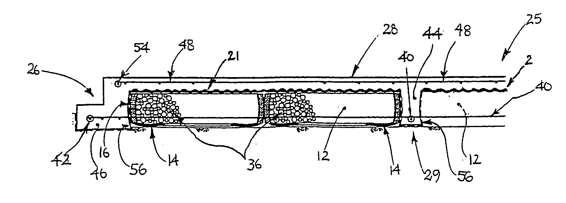
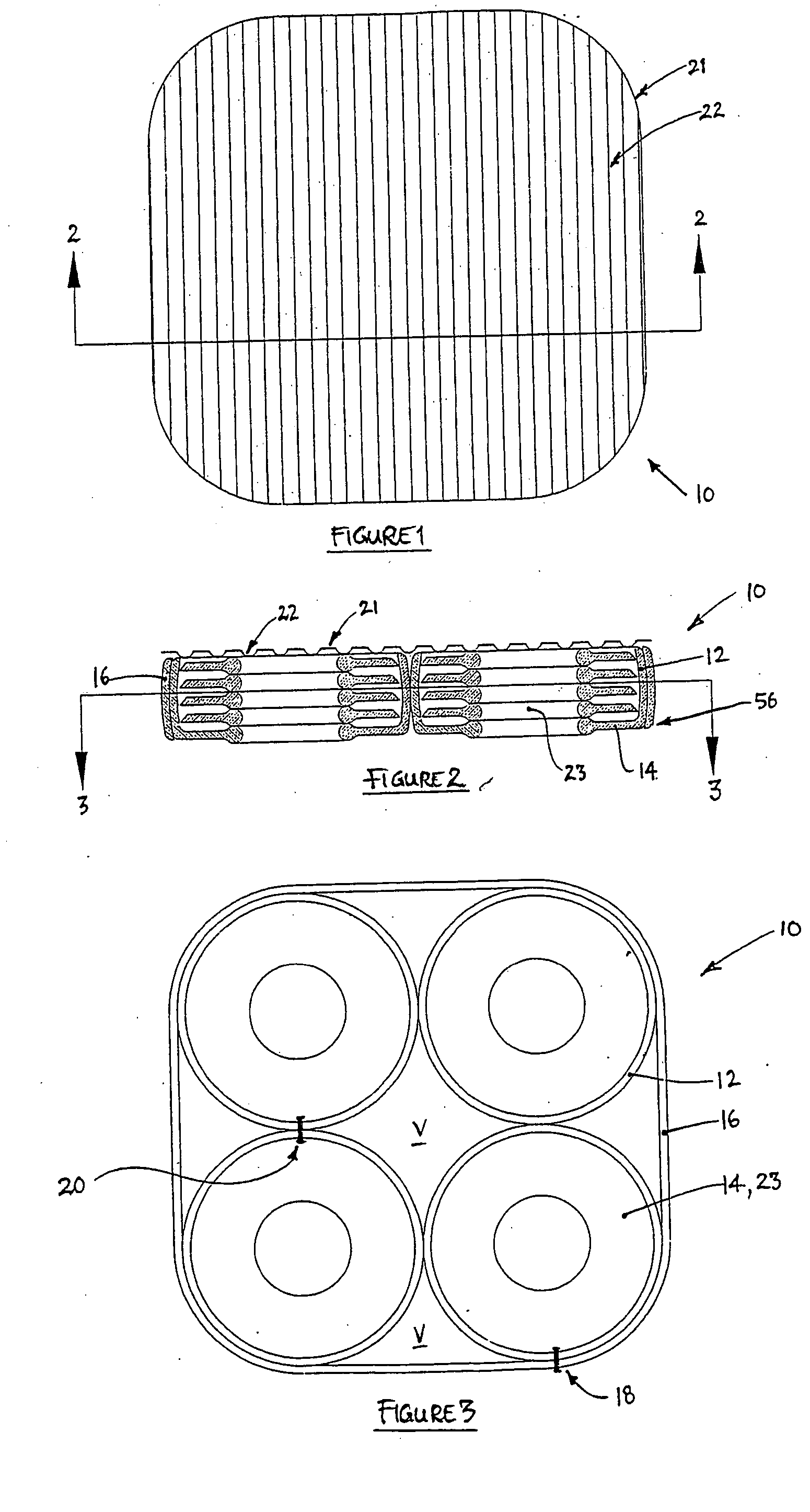
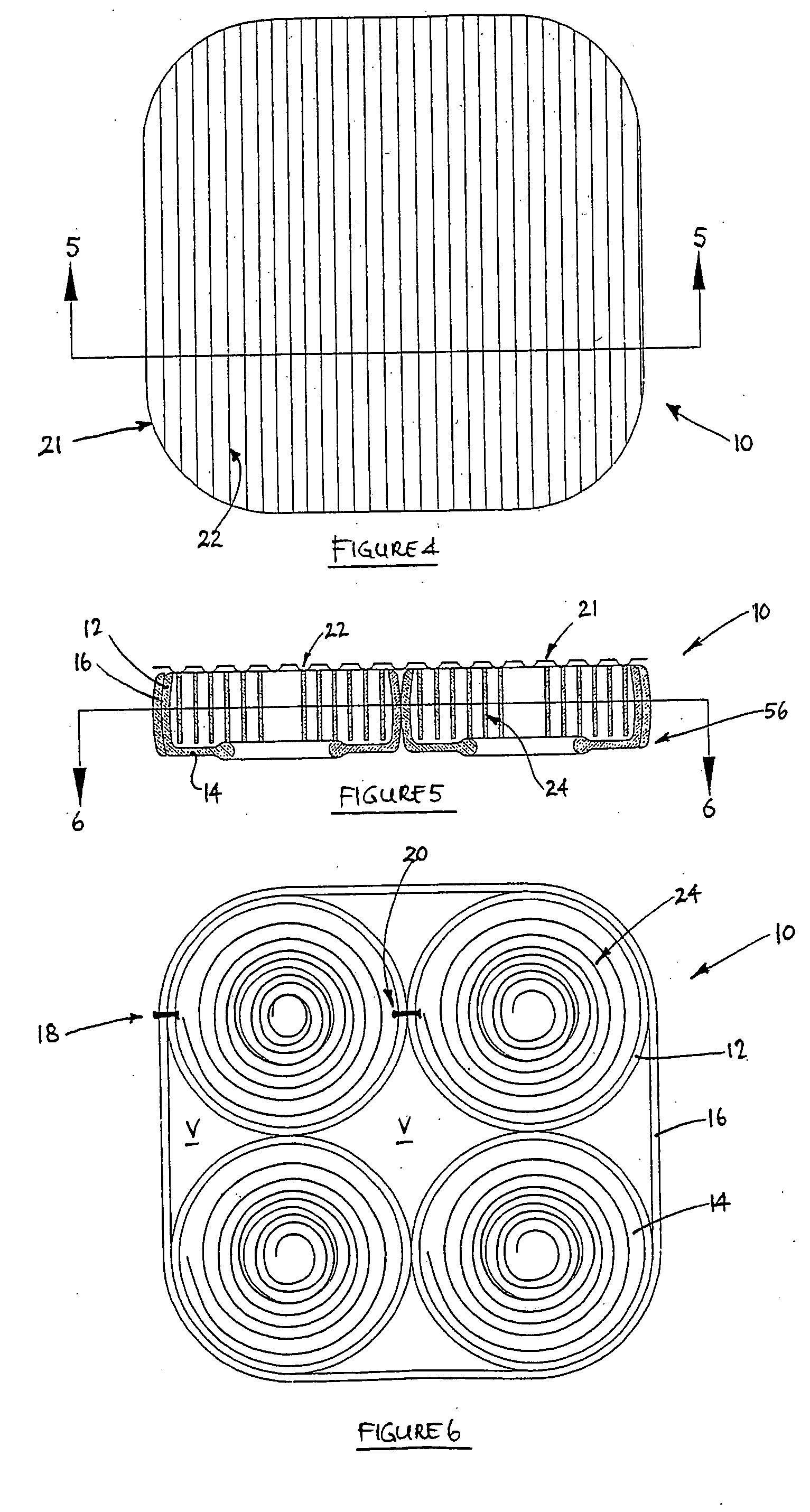
[0061] Referring firstly to FIGS. 1 to 6, a void former lo in accordance with the present invention includes a plurality of, in this case four, tyres 12. Each tyre preferably has an in-use upper tyre side wall removed therefrom (as best seen in FIGS. 2 and 5) and has an in-use lower side wall 14 remaining intact. A retention element in the form of one or more lengths of tyre tread 16 or conveyor belt 16 extends around the perimeter of the four tyres as shown, and is attached thereto via a plurality of fastening elements in the form of screws (e.g. Tec Screws), bolts or pins 18 (one such screw / bolt / pin being shown in FIGS. 3 and 5). Alternatively or additionally industrial strength adhesive may be used. In addition, each tyre is attached to each adjacent tyre, at adjacent treads, by screws, bolts or pins 20 (one such screw / bolt / pin being shown in FIGS. 3 and 5).

[0062] A continuous but discrete capping in the form of lid or cap 21 is shown positioned on the void former 10, and is typ...


PUM


Abstract

A void former unit (10) for use in a concrete foundation (25) includes a plurality of tyres (12) located side-by-side. The void former can have a retention element in the form of tyre tread or conveyor belt (16) located around the perimeter of the plurality of tyres. Typically, each tyre has an in-use upper side wall removed therefrom, thus enabling a fill material (36) to be located within each tyre, and between each tyre and the retention element, and in any voids between the tyres in the unit The improvement comprises arranging a capping element (80) on the unit and / or in-filling the unit with fill material (74,78) formed from tyre or conveyor belt material. The unit can be used in a concrete foundation by arranging one or more of the void former units on the ground and in-filling the units with the fill material and / or covering the units with the capping element prior to concrete pouring.

Description

FIELD OF THE INVENTION [0001] The present invention relates to an improved void former unit for use in concrete foundations. BACKGROUND OF THE INVENTION [0002] Void formers are used to minimise the cost of forming concrete foundations, especially concrete slabs. The use of void formers enables less concrete to be used in forming the slab, whilst reinforcing beams can be defined between adjacent void formers to increase slab strength. [0003] Various void formers are known in the art, including those shown in AU584769, AU585743, AU591816, AU30129 / 92, AU74322 / 91, AU37039 / 89, U.S. Pat. No. 3,109,217, U.S. Pat. No. 3,148,444 and U.S. Pat. No. 4,799,348. [0004] AU710541 discloses the use of vehicle tyres as void formers. The tyres are laid side-by-side to provide a base for a concrete raft slab, and are then overlaid with a mesh which supports a waterproof membrane. Edge and internal beams can also be defined around the tyres, by using a shaped water-impermeable sheet material along the e...

Claims


Application Information

Patent Timeline
24 Nov 2005
Publication
US20050257478A1
IPC
E02D27/02; E04B5/36; E04B5/48
CPC
E02D27/02; E04B5/48; E04B5/36
Inventors
CALLINAN, GARRY