
Electrical connector for attenuating vibrations, in particular for the injector of a motor vehicle engine
A technology of electrical connectors and connectors, which is applied in the direction of connection, parts and circuits of connection devices, and can solve problems such as wear, increased axial movement of connectors and sockets, increased movement, etc.
Patent Information
- Authority / Receiving Office
- CN · China
- Patent Type
- Applications(China)
- Current Assignee / Owner
- Publication Date
- 2007-09-05
- Estimated Expiration
- Not applicable · inactive patent
Smart Images
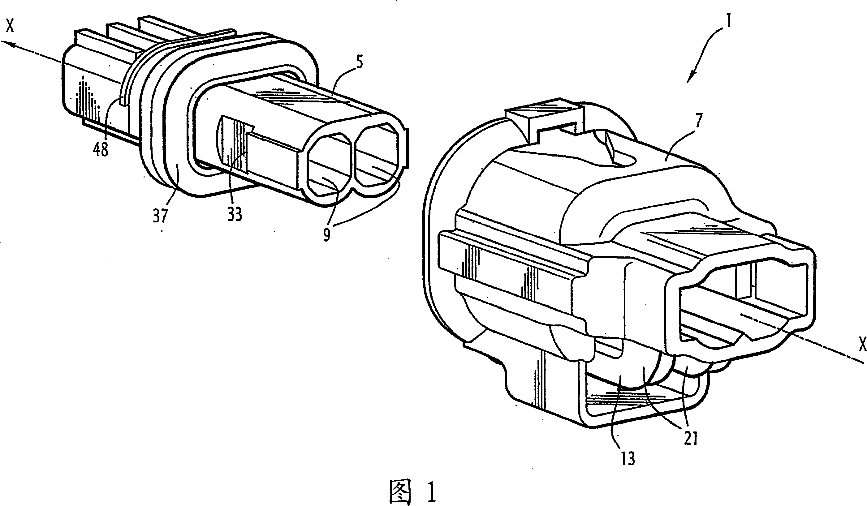
Figure 1 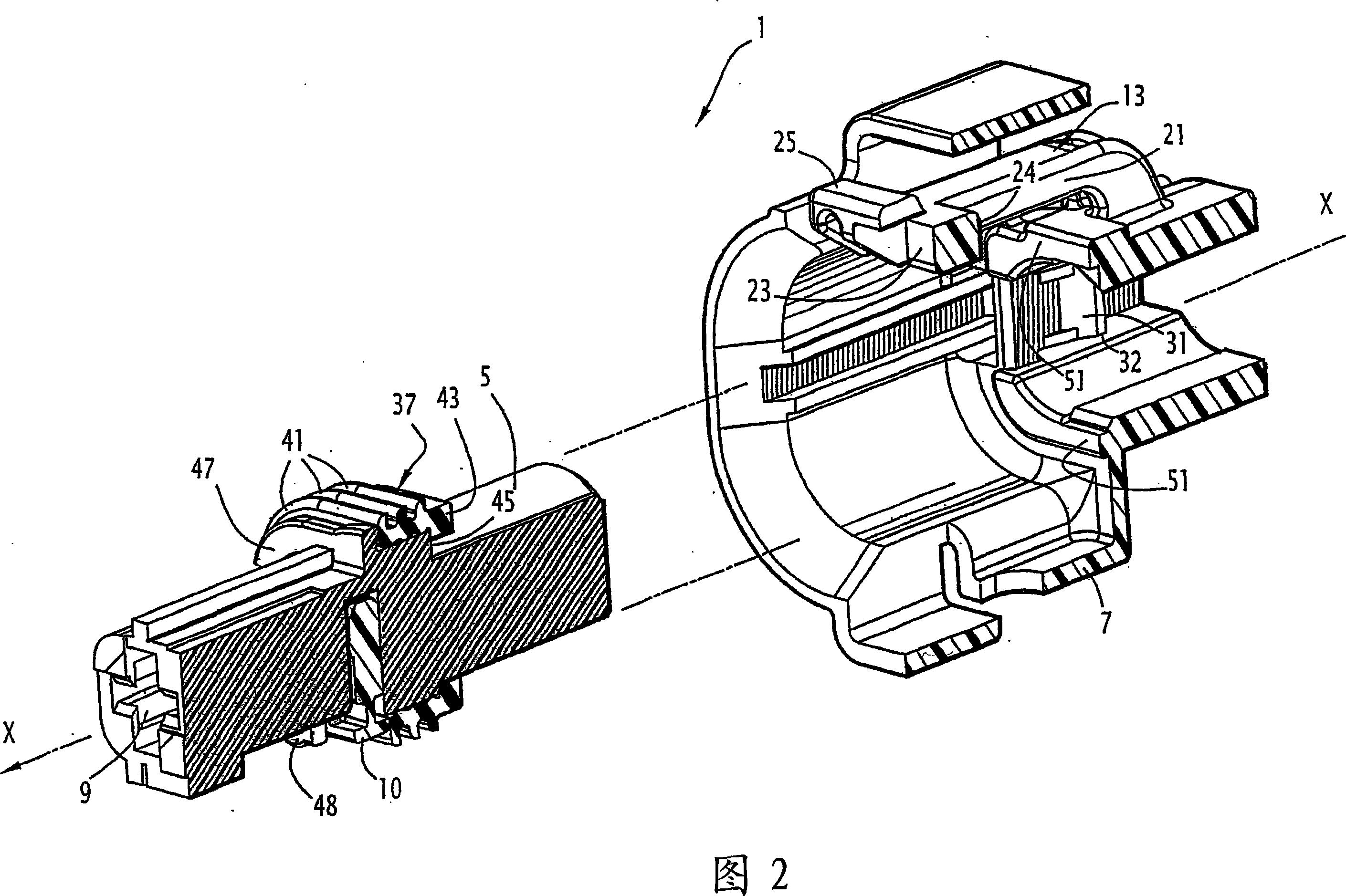
Figure 2 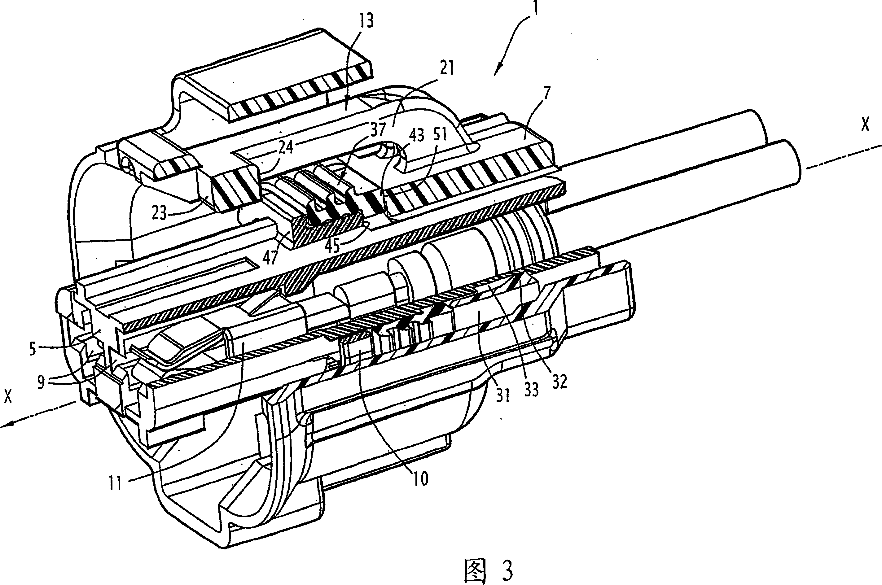
Figure 3
Abstract
Description
technical field
[0001] The present invention relates to an electrical connector designed to be coupled with a counterpart of the connector by elastic interlocking along the coupling direction, for which purpose the electrical connector comprises locking by elastic interlocking and Means having an axial stop surface arranged to form, with a stop surface associated with a complementary locking means of a counterpart, a mutual support against disconnection of the connector and counterpart. Background technique
[0002] In certain applications in harsh environments, especially in the case of connection technology for the engine compartment of a motor vehicle, the quality of the electrical contacts can deteriorate rapidly and fail.
[0003] In the particular example of a connection device for an injector of an internal combustion engine, the connection socket fixed to the engine is subjected to high levels of vibration and also very high levels of temperature.
[0004] For exist...
Examples
Embodiment Construction
[0026] An electrical connector consistent with a first embodiment of the invention is shown in FIGS. 1 to 6 .
[0027] In the example shown, the connector 1 is a two-way connector for an injector of a motor vehicle internal combustion engine, which connector is arranged to couple with a socket 3 ( FIGS. 5 and 6 ) forming the counterpart of the connector. .
[0028] In all the figures we introduce an X-axis which corresponds to the coupling direction and is oriented along the direction of the connector towards the receptacle engagement. The terms "front" and "rear" employed hereinafter should be understood in relation to this orientation, and it is assumed that the connector engages on the receptacle by a movement from rear to front.
[0029] The terms "axial" and "transverse" should also be understood in relation to this X-axis.
[0030] In a first embodiment of the invention represented in Figures 1 to 6, a connector 1 comprises a contact-carrying module 5 and a housing 7, ...