
Pneumatic tire and tire mold
A technology for pneumatic tires and forming molds, applied to tire treads/tread patterns, tire parts, tires, etc., can solve problems such as stone trapping, crack damage at the bottom of grooves, and entry, etc., and achieve excellent WET performance, excellent The effect of anti-stone trapping
Patent Information
- Authority / Receiving Office
- CN · China
- Patent Type
- Applications(China)
- Current Assignee / Owner
- Publication Date
- 2008-04-09
- Estimated Expiration
- Not applicable · inactive patent
Smart Images
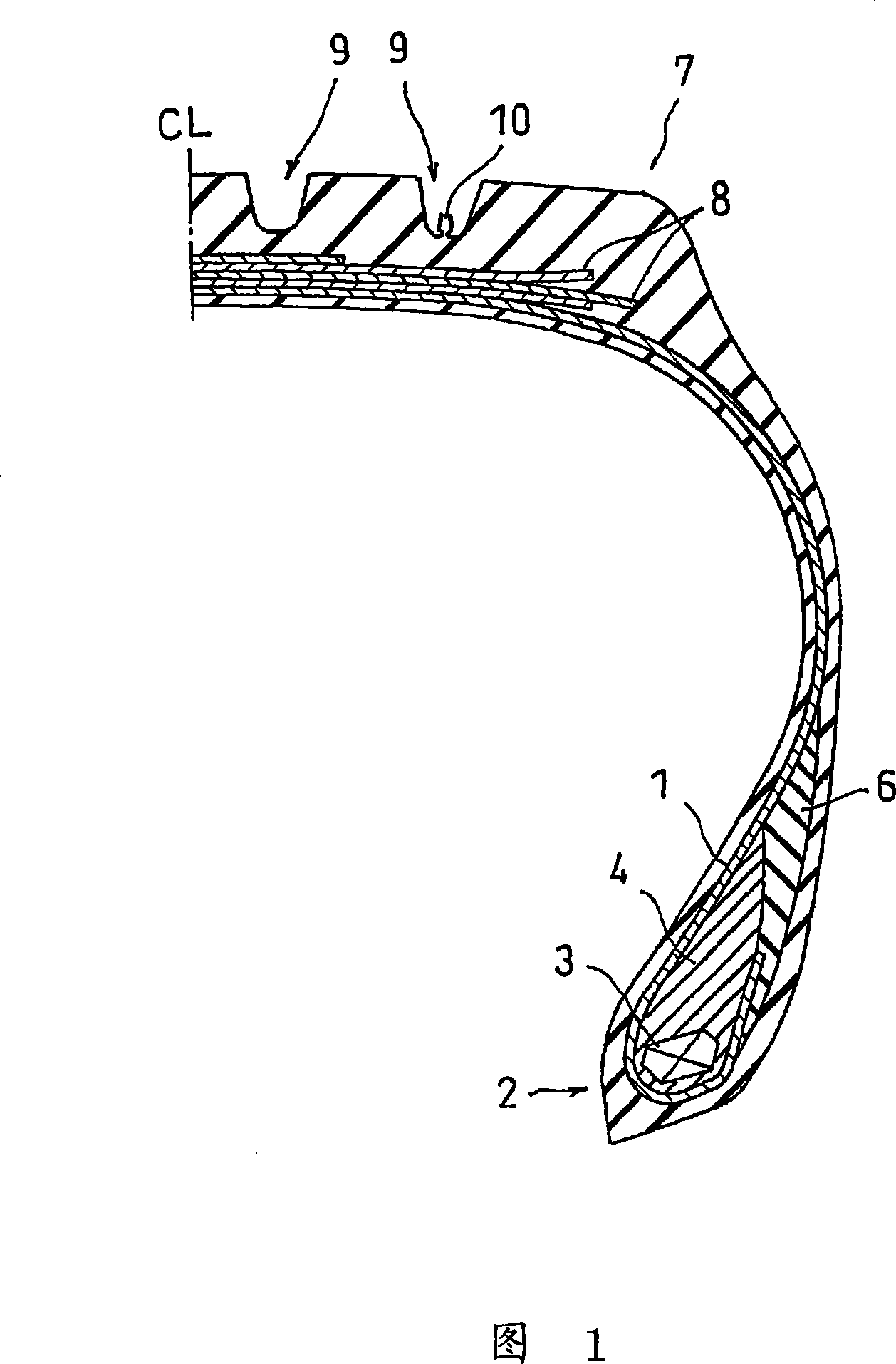
Figure 1 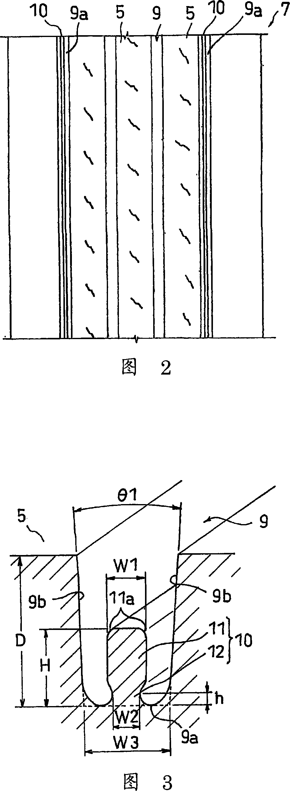
Figure 2 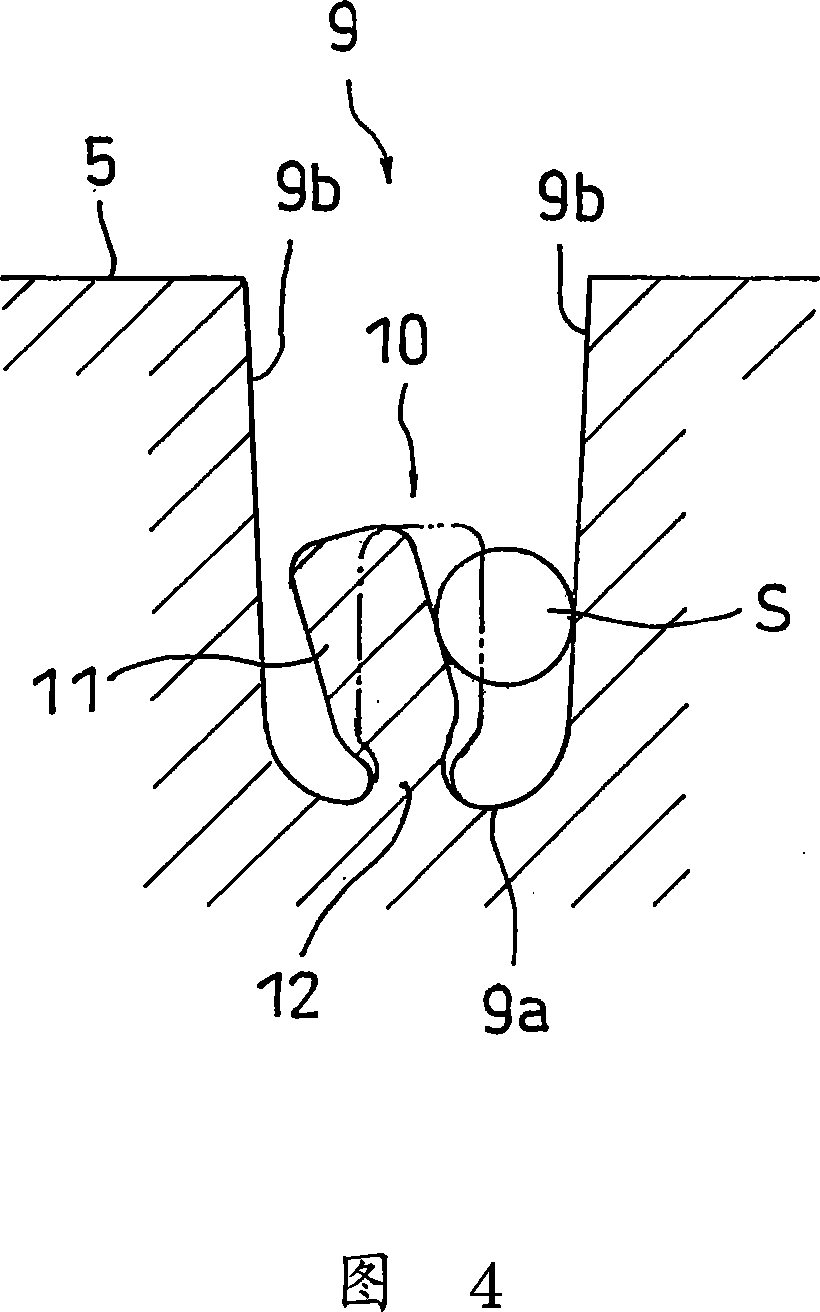
Figure 3
Abstract
Description
technical field
[0001] The present invention relates to a pneumatic tire having a ridge provided at the groove bottom of a tread groove portion, and a tire molding die for molding the pneumatic tire. Background technique
[0002] Usually, the tread of a pneumatic tire is provided with grooves such as circumferential grooves and lateral grooves, and land portions divided by the grooves, so that various tread patterns corresponding to the required tire performance and service conditions are formed. . This kind of groove has the problem that when driving on uneven gravel roads, stones on the road are sometimes caught in the groove, and when the tire rolls in this state, it is repeatedly pushed to expand the groove. The internal force, or the trapped stones enter the bottom of the ditch, causing damage such as cracks at the bottom of the ditch.
[0003] As described in the following patent documents 1 to 3, in order to deal with this problem, a technique has been proposed in w...
Examples
no. 1 Embodiment approach
[0051] Fig. 1 is a tire meridian half sectional view showing an example of a pneumatic tire of the present invention. Fig. 2 is a developed view of the tread of the pneumatic tire. Fig. 3 is a sectional oblique view when a part of Fig. 1 is enlarged and viewed obliquely.
[0052] As shown in Figures 1 and 2, in this embodiment, on the outer peripheral side surface of the tread portion 7, that is, on the tread, a circumferential groove 9 as a groove portion is continuously provided along the tire circumferential direction, and the circumferential groove 9 divides The resulting land portion has a rib pattern with the rib 5 as the main tone. On the groove bottom 9 a of the outermost circumferential groove 9 in the tire width direction among the four circumferential grooves 9 , protrusions 10 are provided extending in the extending direction of the circumferential groove 9 , that is, in the tire circumferential direction.
[0053] As shown enlarged in FIG. 3 , the protrusion 10 ...
no. 2 Embodiment approach
[0073] The structure of the second embodiment is the same as that of the first embodiment except for the following structures of the groove portion and the ridge, so the common points will be omitted and the differences will be mainly described. In addition, the same reference numerals are assigned to the same members as those described in the first embodiment, and overlapping descriptions will be omitted.
[0074] As shown in FIG. 6 , the protrusion 20 includes a crown 21 constituting the upper body and a base 22 constituting the lower body. The crown 21 has a substantially circular cross-section, protrudes toward the outer peripheral side of the tire, and is formed by a curved surface that protrudes toward the groove wall 9b side from the front end to the side. The shape of the base 22 is substantially the same as that of the base 12 of the first embodiment, and integrally connects the crown 21 and the groove bottom 9a.
[0075] In the present embodiment, since the protrusi...
no. 3 Embodiment approach
[0078] The structure of the third embodiment is the same as that of the first embodiment except that the grooves and ridges have the following structures, so the common points will be omitted and the differences will be mainly described. In addition, the same reference numerals are assigned to the same members as those described in the first embodiment, and overlapping descriptions will be omitted.
[0079] As shown in FIG. 7 , the protrusion 30 includes a crown 31 constituting the upper body and a base 32 constituting the lower body. The crown 31 has a substantially rectangular cross-section and protrudes toward the tire outer peripheral side with a protrusion height smaller than that of the crown 11 in the first embodiment. The shape of the base 32 is substantially the same as that of the base 12 of the first embodiment, and integrally connects the crown 31 and the groove bottom 9a.
[0080] In this embodiment, the groove wall angle θ2 of the circumferential groove 9 is set...