
Switching mechanism of pneumatic nailing machine
A switch mechanism and trigger technology, applied in nailing tools, manufacturing tools, etc., can solve the problems of pneumatic nailing machine batter and other problems, and achieve the effect of reducing processing cost, using safety, and improving the qualification rate of one-time installation.
Patent Information
- Authority / Receiving Office
- CN · China
- Patent Type
- Applications(China)
- Current Assignee / Owner
- Publication Date
- 2010-12-01
- Estimated Expiration
- Not applicable · inactive patent
Smart Images
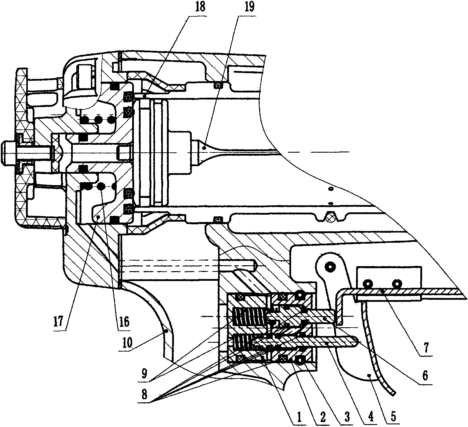
Figure 1 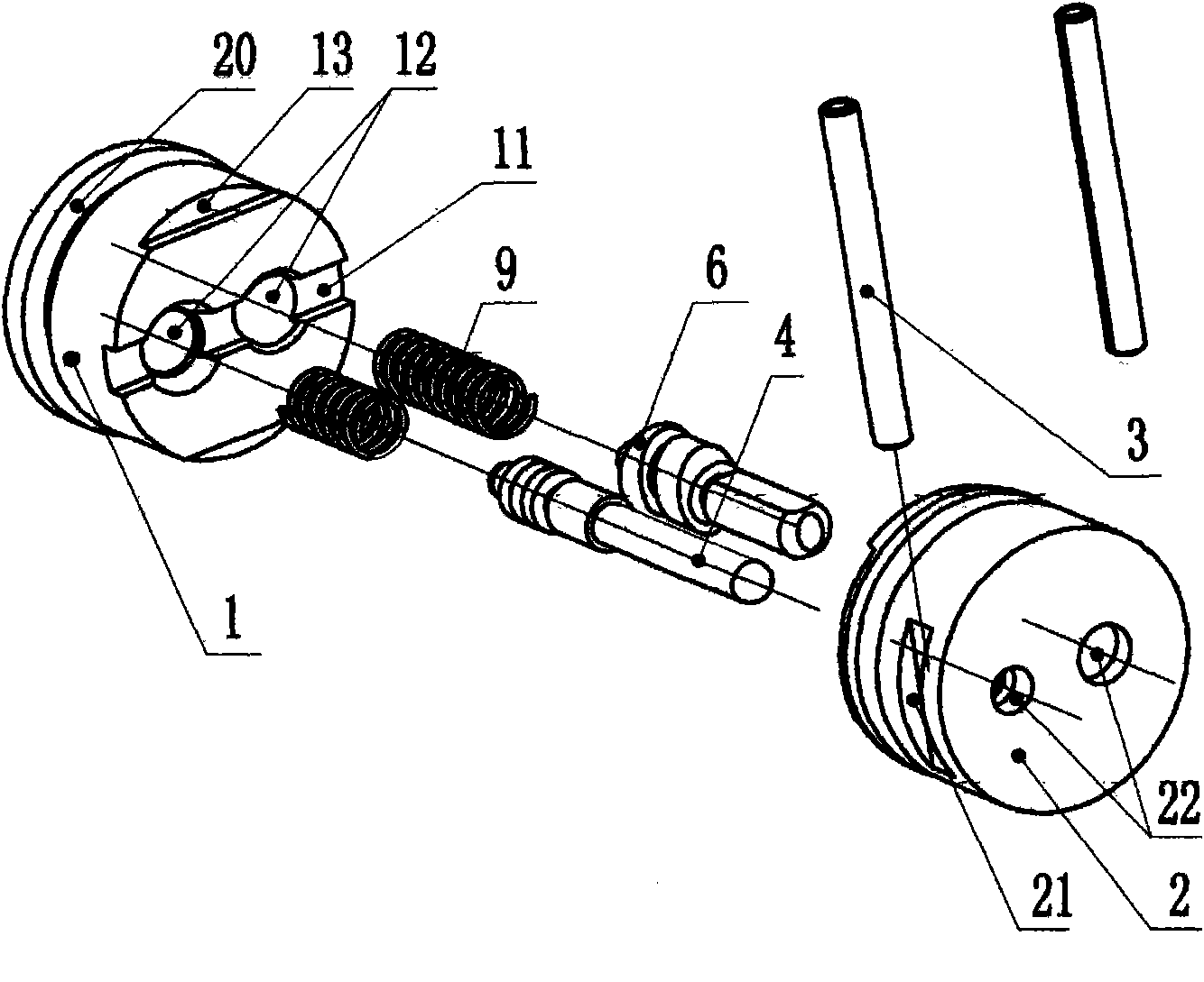
Figure 2 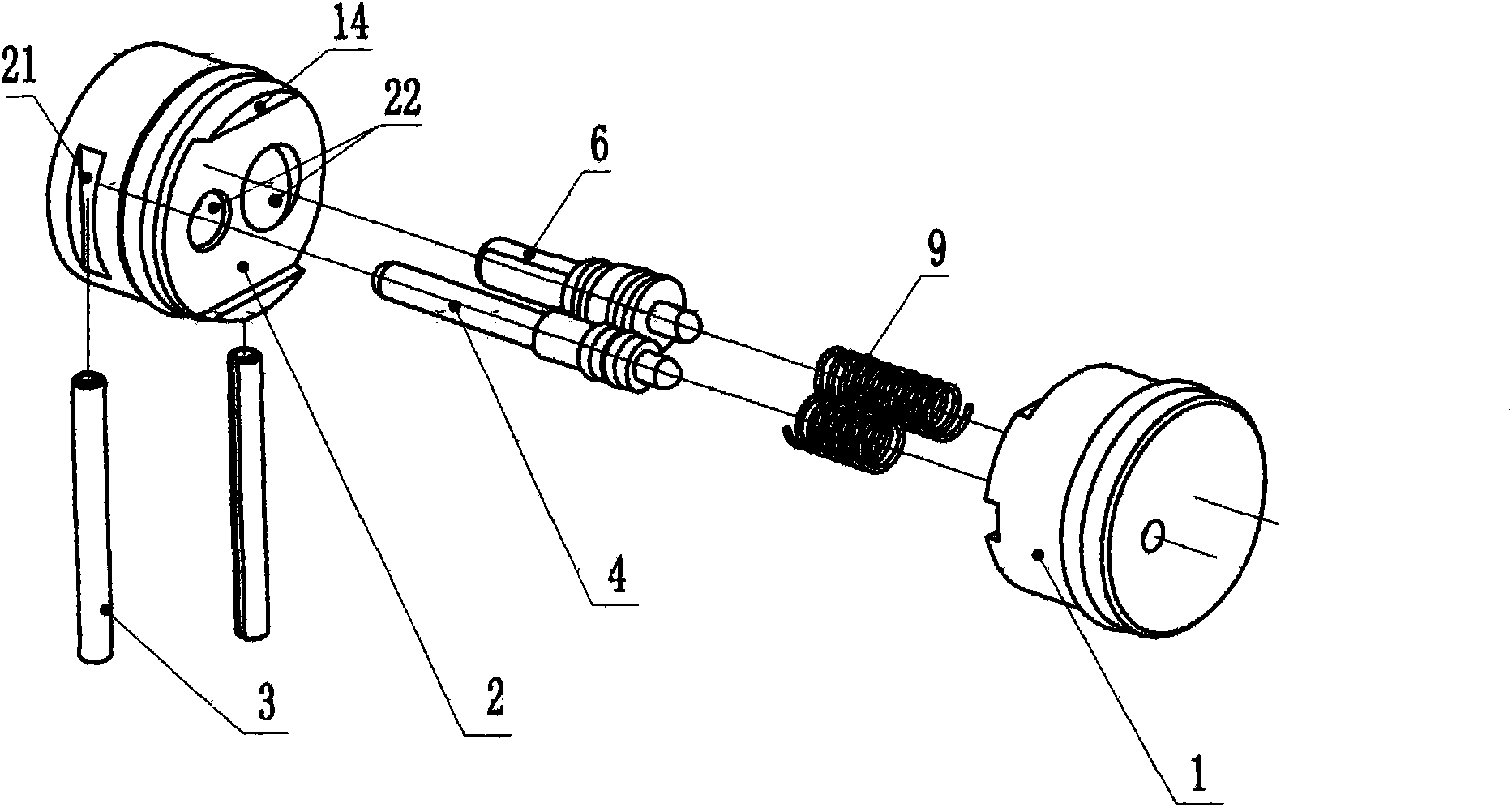
Figure 3
Abstract
Description
technical field
[0001] The invention relates to a switch mechanism of a pneumatic nailing machine, in particular to a switch mechanism with a safety function controlled by a safety component. Background technique
[0002] Pneumatic nailing machines with insurance and switch mechanisms currently on the market are nothing more than the following two structures:
[0003] 1. Add a safety buckle under the trigger. When the safety buckle is screwed to the bottom of the trigger, if the trigger is not in place, nailing cannot be performed; when nailing, the gas in the balance valve is also discharged through the switch rod.
[0004] 2. Add a safety sheet on the trigger. Only through the action of the safety sheet can the safety mechanism perform the nailing work under the condition of pressing the trigger. When nailing, the gas in the balance valve is also discharged through the switch rod.
[0005] The above two insurance institutions have their own shortcomings:
[0006] The fir...
Examples
Embodiment Construction
[0025] Such as figure 1 , figure 2 , image 3 , Figure 4 As shown, the present invention is mainly composed of an upper air guide sleeve 1, a lower air guide sleeve 2, an elastic cylindrical pin 3, a trigger 5, a safety frame assembly 7, an "O" ring 8, and a valve stem compression spring 9; Roots are the lower valve stem 4 and the upper valve stem 6 respectively. The upper air guide sleeve 1 is provided with an outer ring groove 20 on its periphery, and an "O" ring 8 is installed on the outer ring groove for sealing with the housing 10. The middle groove 11 opened in the middle of the front side plays the role of air flow direction. Two holes 12 are also arranged in the middle to play a guiding and sealing role, and two sunken steps 13 cooperate with the lower air guide sleeve 2 . The lower air guide sleeve 2 plays the role of sealing and fixing the upper air guide sleeve 1. Two outer grooves 21, two bosses 14 and two holes 22 are arranged on both sides of the lower air ...