
Tank bottom vacuum sampling ball valve
A sampling ball and vacuum technology, applied to the valve details, valve device, valve shell structure, etc., can solve the problems of difficult maintenance, poor sealing of the valve plate, and easy air leakage of the shaft, so as to achieve a compact structure of the valve body and prevent burns Effect
Patent Information
- Authority / Receiving Office
- CN · China
- Patent Type
- Patents(China)
- Current Assignee / Owner
- Publication Date
- 2014-09-17
Smart Images
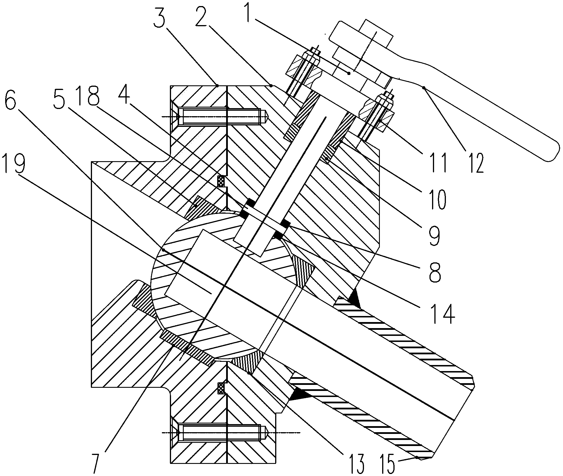
Figure 1 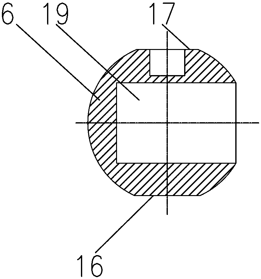
Figure 2
Abstract
Description
technical field
[0001] The invention relates to a valve body suitable for various tank bottom vacuum sampling working conditions, in particular to a tank bottom vacuum sampling ball valve. Background technique
[0002] Generally, valves with a nominal pressure lower than the standard atmospheric pressure are called vacuum valves. These valves are mainly used in vacuum negative pressure systems, condensation and high-pressure drainage systems, and are used as opening and closing isolation devices to ensure good isolation between the system and the atmosphere. At present, vacuum gate valves and vacuum globe valves are the most commonly used in the market. However, when the gate valve is closed, the valve plate is not tightly sealed and the axis is prone to air leakage, so there is a certain risk in use, and the overall size is large, and maintenance is difficult; the flow resistance of the stop valve is large, and the force required for opening and closing is relatively large ...
Examples
Embodiment Construction
[0015] The present invention will be further described below with reference to the specific drawings and embodiments.
[0016] As shown in the figure: the tank bottom vacuum sampling ball valve includes an upper valve body 3, a lower valve body 2, an upper valve seat 5, a lower valve seat 13 and a valve ball 6, and the upper valve body 3 and the lower valve body 2 are fixedly connected. The upper valve body 3 is equipped with an upper valve seat 5, an upper ball valve bearing 7 and a stem thrust bearing 8, and a lower valve seat 13 and a lower ball valve bearing 14 are installed in the lower valve body 2, and the upper valve seat 5 and the lower valve seat A valve ball 6 is installed between 13, a sampling cavity 19 is opened in the valve ball 6, a first plane 16 and a second plane 17 are opened on the valve ball 6, and the valve ball 6 sits on the ball valve bearing through the first plane 16 7, the valve ball 6 sits on the lower ball valve bearing 14 through the second plane...