
Oil immersion device of transformer
A technology for transformers and oil immersion, which is applied to devices for coating liquid on the surface, manufacturing of inductors/transformers/magnets, electrical components, etc. The effect of stability and leveling
Patent Information
- Authority / Receiving Office
- CN · China
- Patent Type
- Patents(China)
- Current Assignee / Owner
- Publication Date
- 2015-06-03
- Estimated Expiration
- Not applicable · inactive patent
Smart Images
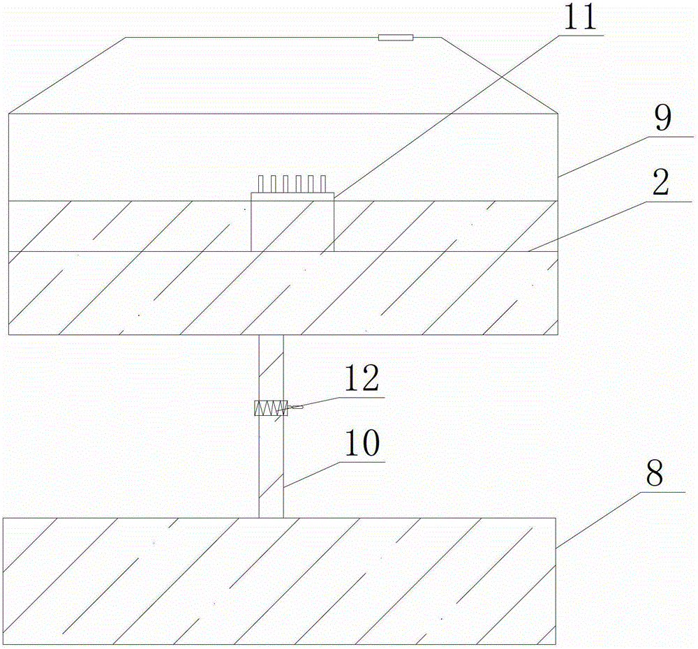
Figure 1 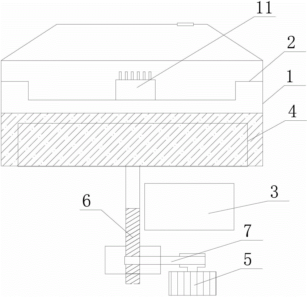
Figure 2 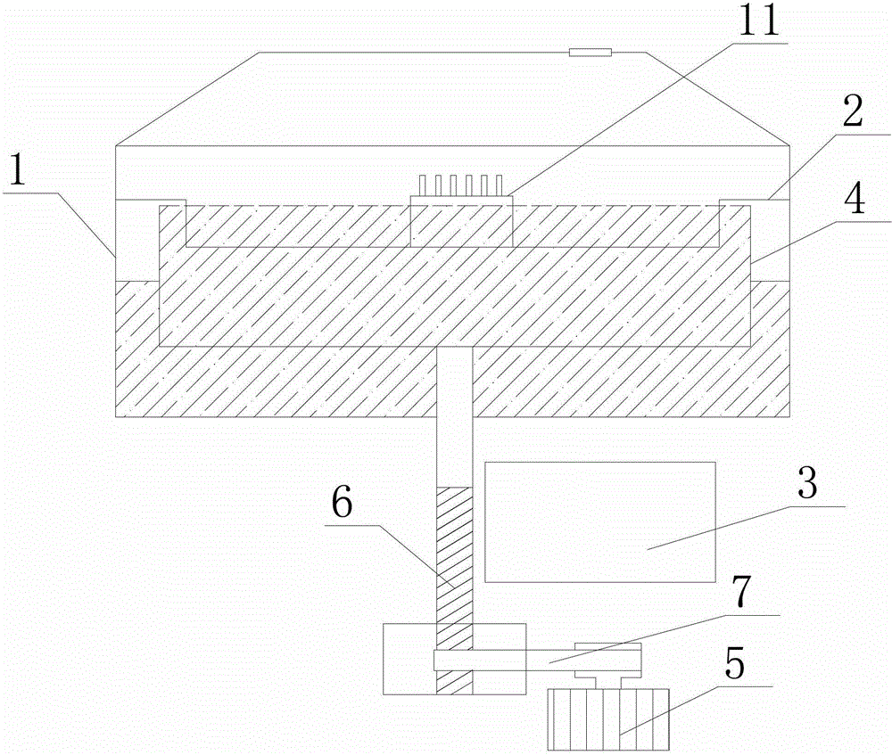
Figure 3
Abstract
Description
technical field
[0001] The invention relates to an oil immersion device for a transformer. Background technique
[0002] Such as figure 1 As shown, the traditional transformer impregnated insulating oil device includes a vacuum cylinder 9 and an oil cylinder 8 arranged below it. The oil cylinder 8 and the vacuum cylinder 9 are connected by a pipe 10 , and a valve 12 is provided on the pipe 10 . A support 2 for placing a transformer 11 is arranged inside the vacuum cylinder 9 . Its working principle is: the oil cylinder 8 storing insulating oil and the vacuum cylinder 9 are separated. When in use, the vacuum cylinder 9 is pumped into a negative pressure vacuum by an air compressor, and the insulating oil is drawn from the lower oil cylinder 8 by pressure. Pumped into the vacuum cylinder 9 storing the transformer 11 through a pipe 10, controlled by the opening size of a valve 12, the liquid level of the oil is visually measured with human eyes, and the valve 12 is closed aft...
Examples
Embodiment Construction
[0013] Specific embodiments of the present invention will be described in detail below in conjunction with the accompanying drawings.
[0014] Such as figure 2 , image 3 As shown, the oil immersion device of the transformer according to the present invention includes an oil tank 1, a support 2 and a PLC control system 3 fixed in the oil tank 1 with a downwardly recessed middle part, and a recessed part is set in the middle part of the support 2 for shelving the transformer 11. The edge is higher than where the transformer 11 is located, and the upper edge of the sub-slot 4 will not touch the support 2 when it rises, so that the transformer 11 can be located in the sub-slot 4 and contact the insulating oil. Because the PLC control system 3 has no requirements on the position, it can be set at any position that can be placed. Described oil groove 1 is provided with sub-groove 4, and sub-groove 4 is positioned at the below of support 2, and the outer side of oil groove 1 is p...