
Forced rolling mill feed device
A feeding device and rolling mill technology, applied in metal rolling, metal rolling, metal processing equipment and other directions, can solve the problems of late start of rare refractory metal sheet production, inability to meet the requirements of rolling mill bite, and high labor intensity of workers. , to achieve the effect of reducing labor intensity, simple structure and high degree of automation
Patent Information
- Authority / Receiving Office
- CN · China
- Patent Type
- Patents(China)
- Current Assignee / Owner
- Publication Date
- 2015-03-25
Smart Images
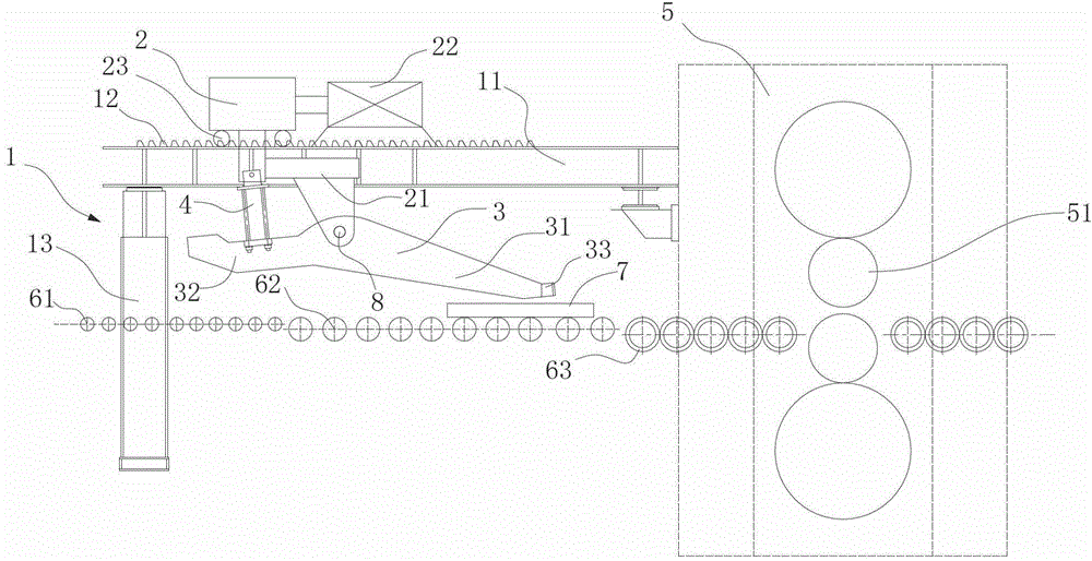
Figure 1 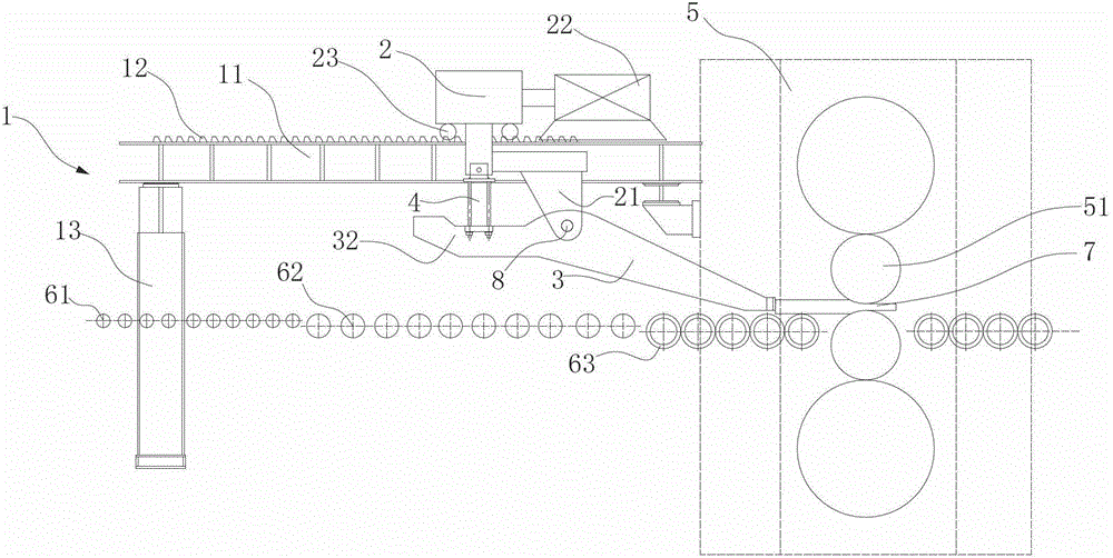
Figure 2
Abstract
Description
technical field
[0001] The invention relates to a feeding device for the production of metal plates, in particular to a forced feeding device for rolling mills for the production of refractory metal plates. Background technique
[0002] With the rapid development of modern science and technology, rare refractory metals are widely used in aerospace industry, electronics industry, atomic energy industry and other fields due to their unique strength, hardness, electrical conductivity, thermal conductivity, and excellent shock resistance and corrosion resistance. Its important value is increasingly reflected; the application of high-quality wide-width rare refractory metal plates has been further improved. However, in terms of the overall processing technology of its plates, there is still a certain gap compared with the advanced countries in the world in terms of technological level, equipment capacity and product structure.
[0003] The unique physical, chemical, and mechanic...
Examples
Embodiment Construction
[0018] The present invention will be further described below in conjunction with the accompanying drawings and embodiments.
[0019] Such as figure 1 As shown, the rolling mill forced feeding device provided by the present invention includes a support stand 1, a translation trolley 2, and a lifting frame 3; the support stand 1 is provided with a suspension 11; the translation trolley 2 is arranged on the suspension 11; The elevating frame 3 is connected to the translation trolley 2 through the elevating device 4, and the elevating frame 3 is located below the suspension 11.
[0020] Such as figure 1 As shown, the lifting frame 3 of the forced feeding device of the rolling mill is in a raised state when the pusher section 31 is not working, and the lower end of the pusher section 31 forms a running channel for the rolled piece 7 . In the working state, the rolling piece 7 is transported to the corresponding position at the lower end of the lifting frame 3 by the transport dev...