
Detection tool for measuring sediment of bored pile
A technology for detection tools and bored piles, which is applied in surveying, earthwork drilling, boreholes/well components, etc., can solve the problems of lack of low-cost bored pile sediment, increase construction costs, and high instrument cost, and achieve simple structure, The effect of long service life and simple detection method
Patent Information
- Authority / Receiving Office
- CN · China
- Current Assignee / Owner
- Publication Date
- 2013-10-02
- Estimated Expiration
- Not applicable · inactive patent
Smart Images
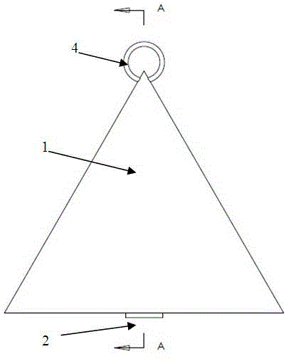
Figure 1 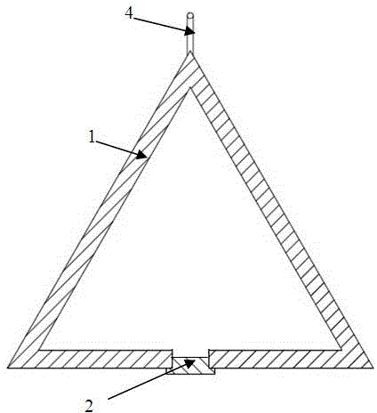
Figure 2 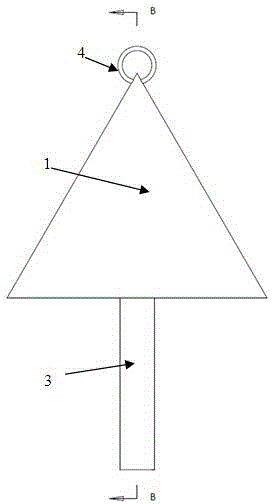
Figure 3
Abstract
Description
technical field
[0001] The invention belongs to the technical field of building measurement, and in particular relates to a detection tool for bored pile sediment measurement. Background technique
[0002] With the development of China's railways, higher requirements are put forward for foundation engineering, especially bored pile foundations. Accurately measuring the sediment at the bottom of bored piles is an effective way to ensure and improve the quality of bored piles. At present, the detection methods for the sediment state at the bottom of the bored pile hole include the hammer detection method, the sampling box detection method and the sediment meter detection method. There are deficiencies in the use of the three, as follows:
[0003] The measuring hammer detection method needs to be checked frequently before and during use. When there is wear, the number is unclear or the number is displaced, the measuring rope needs to be replaced in time. This method is relat...
Examples
Embodiment Construction
[0028] specific implementation
[0029] The structure of the present invention will now be described in detail in conjunction with the accompanying drawings.
[0030] see figure 1 with image 3 , a detection tool for bored pile sediment measurement, including a measuring rope, a heavy cone block 1, a flat bottom cover 2 and a probe 3; wherein,
[0031] see Figure 5 , the heavy cone block 1 is a hollow cone; the tip of the heavy cone block 1 is provided with a rope ring 4, and the rope ring 4 is connected with one end of the measuring rope; the bottom surface of the heavy cone block 1 is provided with a bolt hole 5, and the bolt hole 5 Communicate with the cavity inside the heavy cone block 1;
[0032] see Image 6 , the flat bottom cover 2 is a "convex" structure that matches the bolt hole 5;
[0033] see Figure 7 , the probe 3 is a cylinder, and one end of the probe 3 is threaded and matched with the bolt hole 5;
[0034] see figure 2 with Figure 4 , the bolt...