
Test fixture of image sensor chip and with test light source
An image sensor and chip testing technology, applied to the casing of the measuring device, etc., can solve the problems of inaccurate adjustment of the brightness of the LED surface light source, cumbersome operation, low efficiency, etc., to reduce the loss of test yield, uniform brightness, and long service life. Effect
Patent Information
- Authority / Receiving Office
- CN · China
- Patent Type
- Applications(China)
- Current Assignee / Owner
- Publication Date
- 2014-05-21
Smart Images
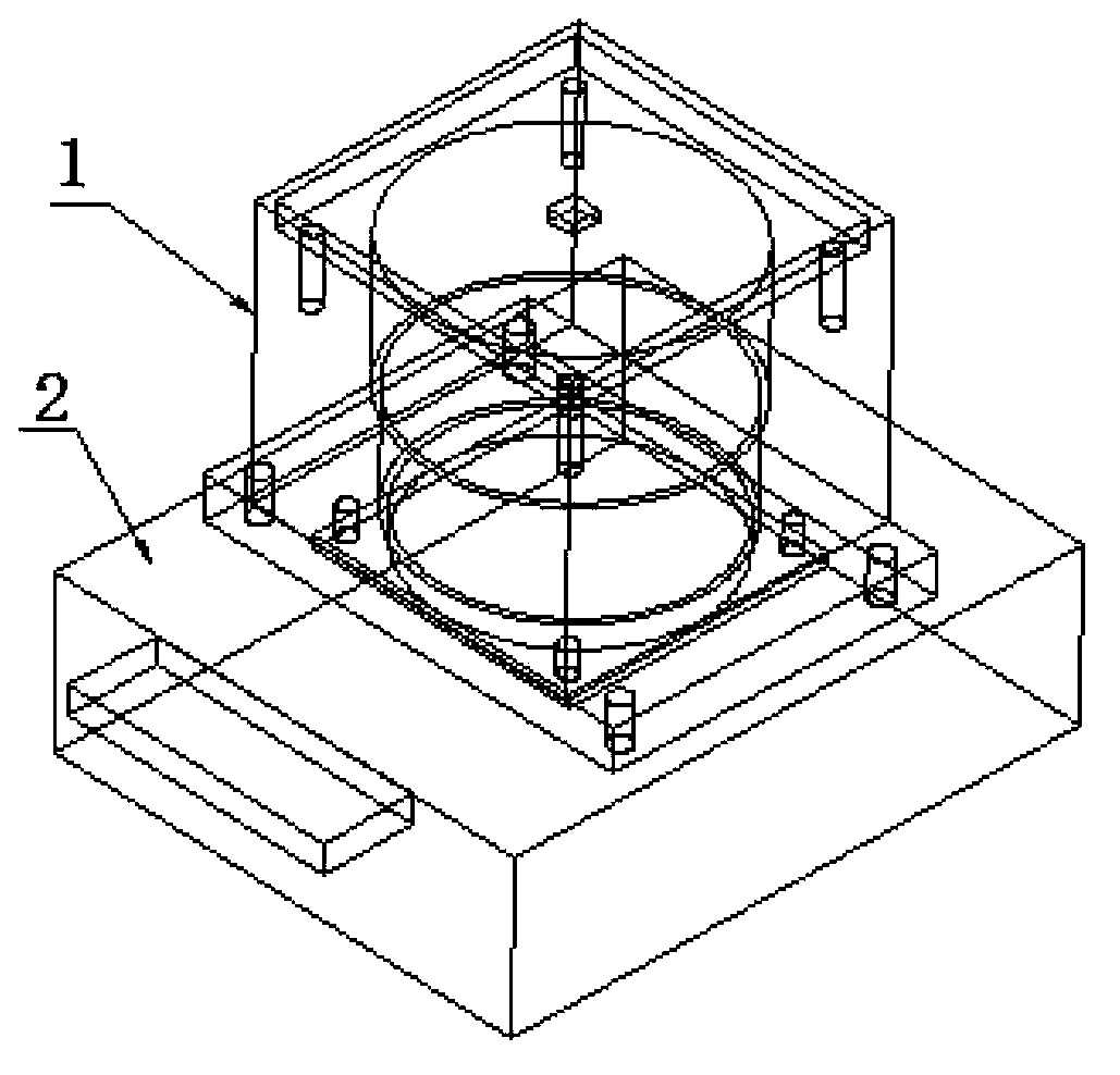
Figure 1 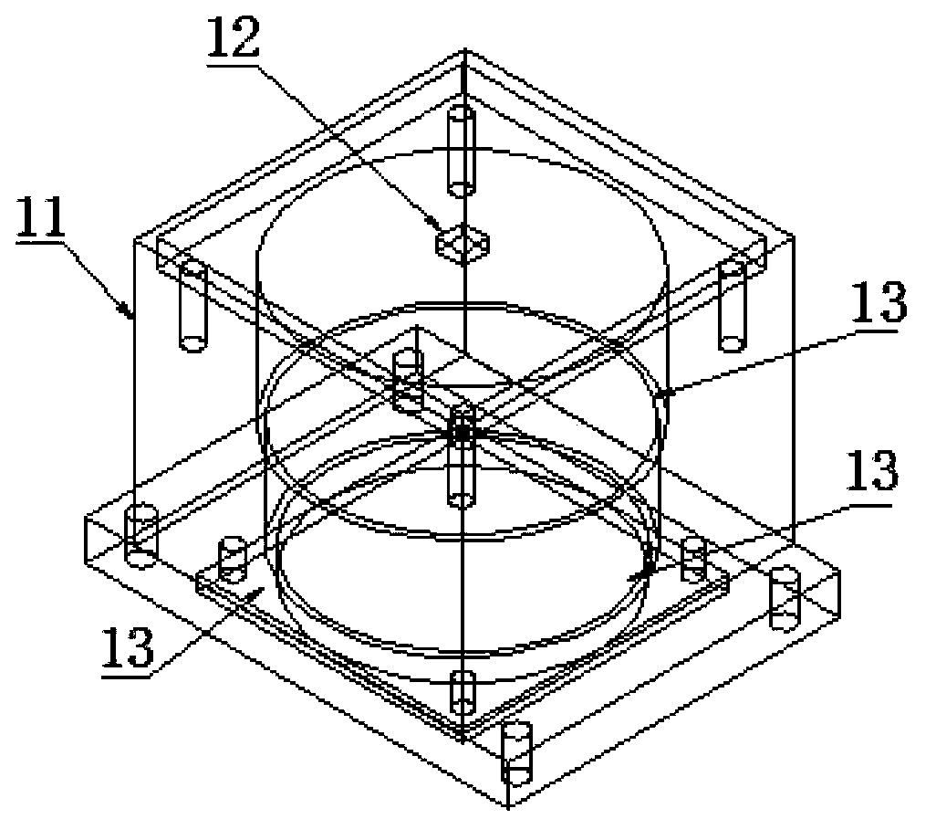
Figure 2
Abstract
Description
technical field
[0001] The invention belongs to the field of single image sensor chip testing, and in particular relates to an improved structure of a test light source and a test fixture for sensor chip testing. Background technique
[0002] In today's situation of image sensor chips being in full swing, in large and small image sensor chip manufacturing enterprises, the chip test light source used must meet two basic conditions: uniformity of light and long service life.
[0003] The semiconductor industry is a fully competitive industry. Products with high performance and low price, that is, high cost performance, are the trump card for enterprises to win in the brutal market competition. Cost reduction is a problem that all companies are considering, and how to bring high profits with low cost is the pursuit of enterprises. The pursuit of cost performance is reflected in everything, and the same is true for the requirements for LED light sources and test fixtures for se...
Examples
Embodiment
[0021] Embodiment: An image sensor chip test fixture with a test light source, including a test light source 1 and a test fixture 2 , the test light source 1 is fixed on the upper end of the test fixture 2 . The test light source is directly installed on the test fixture, without the push and pull action of the traditional LED surface light source, which saves working time and improves the work efficiency of the operator.
[0022] Wherein, the structure of the test light source 1 is as follows: it includes an LED light source frame 11, an LED lamp bead 12 and at least one uniform light plate 13, and the LED light source frame 11 is a metal structure frame of the LED light source (socket LED frame). Both the LED lamp bead 12 and the light uniform plate 13 are located in the LED light source frame 11, the LED lamp bead 12 is located in the inner top center of the LED light source frame 11, and the light uniform plate 13 is located in the LED light source frame 11. 12, the adjace...