
Method and circuit for waking up smart home appliance control system
An intelligent control system and wake-up circuit technology, applied in the direction of electrical program control, program control in sequence/logic controller, electrical components, etc., can solve the limitation of overall aesthetics of product appearance design, increase the complexity of product external structure, reduce Problems such as user operation experience, to achieve the effect of improving the aesthetics of the overall structure, improving the operation experience, saving production technology and difficulty
Patent Information
- Authority / Receiving Office
- CN · China
- Patent Type
- Patents(China)
- Current Assignee / Owner
- Publication Date
- 2017-09-01
Smart Images
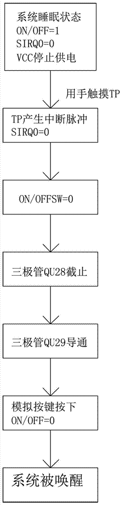
Figure 1 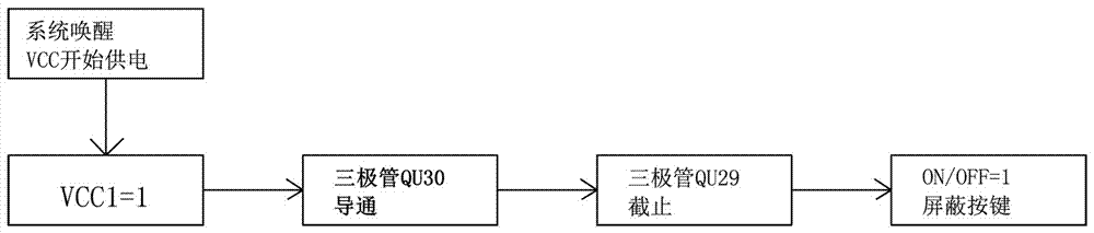
Figure 2 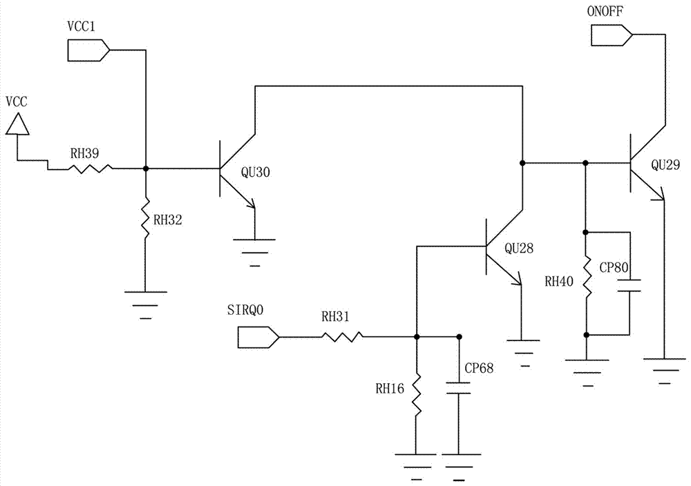
Figure 3
Abstract
Description
technical field
[0001] The invention relates to a system wake-up method and a circuit thereof, in particular to a home appliance intelligent control system wake-up method and a circuit thereof. Background technique
[0002] With the development of science and technology, intelligent control systems are more and more used in home appliances such as refrigerators and air conditioners, usually using Android system as the basic platform, TFT display screen display, and capacitive touch screen operation. Smart home appliances embedded in intelligent control systems bring users a brand-new human-computer interaction experience. As a new generation of home appliances, they have gradually entered the stage of industrialization.
[0003] Users who have used smartphones and tablet computers know that in order to save power, the system has a sleep function. When the system detects that there is no operation for a period of time, it will automatically turn off the display and enter a lo...
Examples
Embodiment Construction
[0032] The content of the present invention will be further described below in conjunction with the accompanying drawings and preferred specific embodiments of the present invention. The examples given are only for explaining the present invention, not for limiting the scope of the present invention.
[0033] Such as Figures 3 to 4 As shown in , the system wake-up circuit described in this solution includes: a startup module that accepts the sensing command sent when the TP is touched, and the startup module outputs a low-level signal to the analog button module after receiving the sensing command, so that the system After the system wakes up, the analog button module converts the received low-level signal into a high-level signal and outputs it to the shielding module for shielding the analog button module; in this specific embodiment, the startup module includes Resistor RH31, resistor RH16 and capacitor CP68, one end of the resistor RH31 is connected to the interrupt pin ...