
Hollow ceramic die and forming method of hollow ceramic component
A ceramic mold and hollow technology, which is applied in the direction of ceramic molding machines, molds, manufacturing tools, etc., can solve the problems that the connecting core cannot be stably fixed, the inner cavity cannot control the precision, and the fit cannot be realized, so as to shorten the embryo-making cycle and save Produce raw materials and overcome the effect of easy collapse
Patent Information
- Authority / Receiving Office
- CN · China
- Patent Type
- Applications(China)
- Current Assignee / Owner
- Publication Date
- 2014-10-08
Smart Images
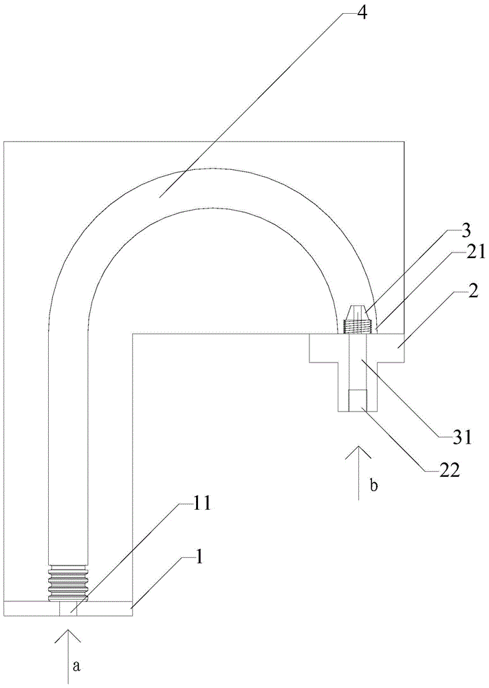
Figure 1 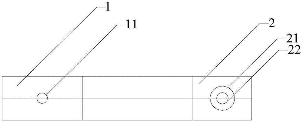
Figure 2 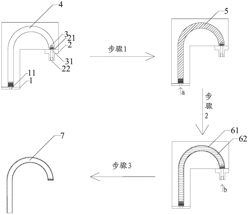
Figure 3
Abstract
Description
technical field
[0001] The invention relates to the field of ceramic molds, in particular to a hollow ceramic mold and a method for forming a hollow ceramic component. Background technique
[0002] In the prior art, there are generally two manufacturing methods for hollow ceramic components with relatively complex shapes, such as a section of elbow, a section of spiral elbow, a section of Y-shaped elbow, or other ceramic components with irregular channels. One is to use the traditional method of grouting and dehumidification of plaster molds to form channels, which is suitable for ceramic components that do not require high molding precision; the other method is to use some organic materials to make connections according to the shape of channels Core parts, use core pulling to fix the connecting parts in the finished mold, and then inject ceramic slurry to make the green body. Before firing, the connecting core parts are eroded by physical or chemical methods to make the req...
Examples
Embodiment 1
[0038] 1. The structure when the cavity of the hollow ceramic mold is U-shaped.
[0039] see figure 1 , the cavity of the hollow ceramic of the present embodiment is a U-shaped cavity, and the mold is a clamping mold, which forms a U-shaped cavity after clamping the molds. One end of the U-shaped cavity is provided with a pouring part 1, and the pouring part 1 is opened. There is a pouring port 11, and the other end of the U-shaped cavity is provided with an air inlet 2, and the air inlet 2 has an air inlet 21, and a core pulling 3 is installed on the air inlet 21, and the core pulling 3 has an outer screw The core-pulling 3 has a cylindrical through-hole 31 in the center of the core-pulling axis, and an air valve 22 is installed in the cylindrical through-hole. The air end faces the outside of the mould, the air intake end of the air valve 22 is connected with an air intake pipe, and the air intake pipe is connected with an external air intake device.
[0040] 2. A method f...