
Water closet with two groups of impellers and design scheme thereof
A design scheme and toilet technology, applied in the field of unpublished patent applications and PCT patent applications, can solve the problems of flushing potential energy waste and other problems, and achieve the effects of high water flow conversion rate, high conversion rate and resistance reduction.
Patent Information
- Authority / Receiving Office
- CN · China
- Patent Type
- Applications(China)
- Current Assignee / Owner
- Publication Date
- 2014-12-17
Smart Images
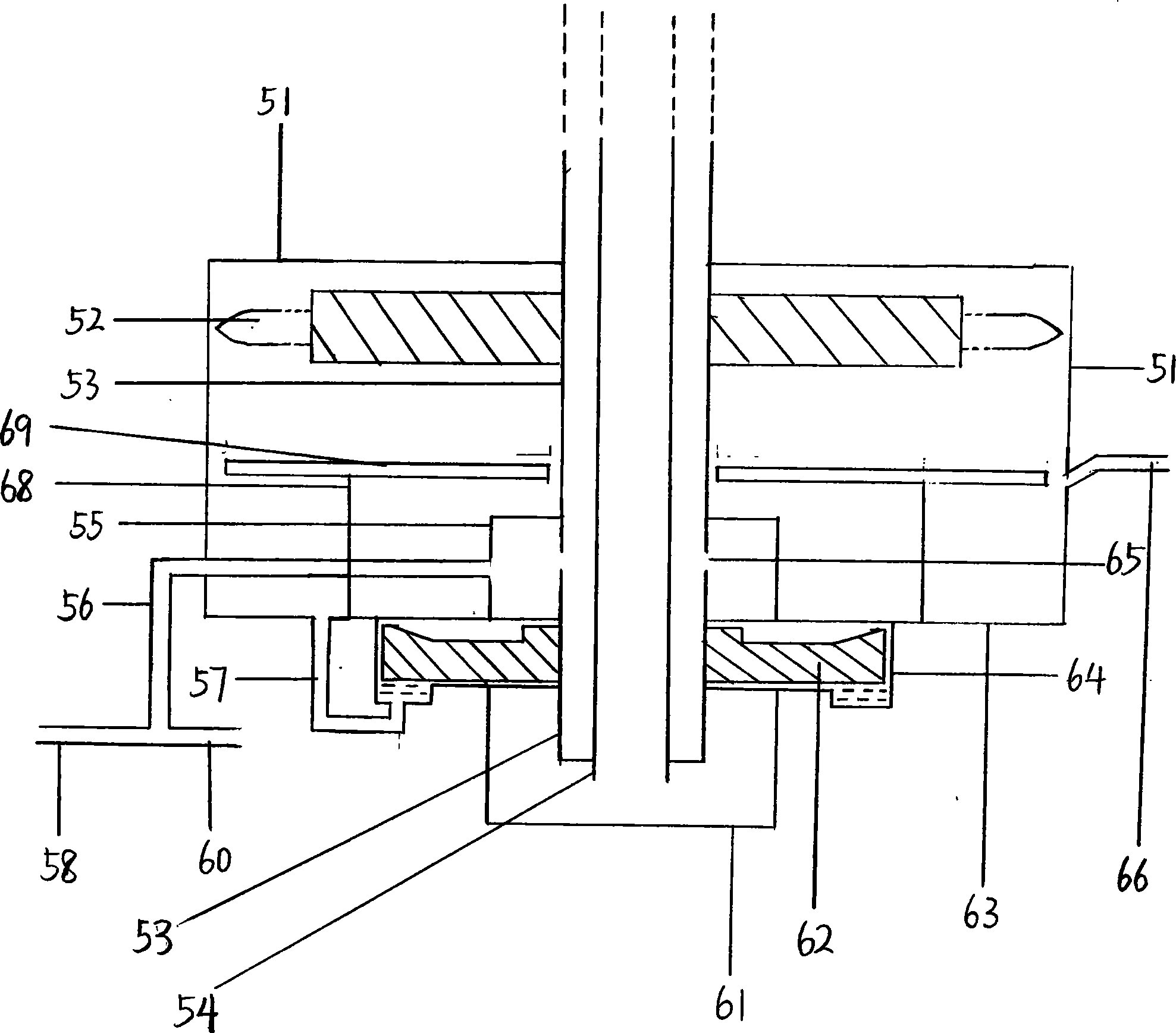
Figure 1 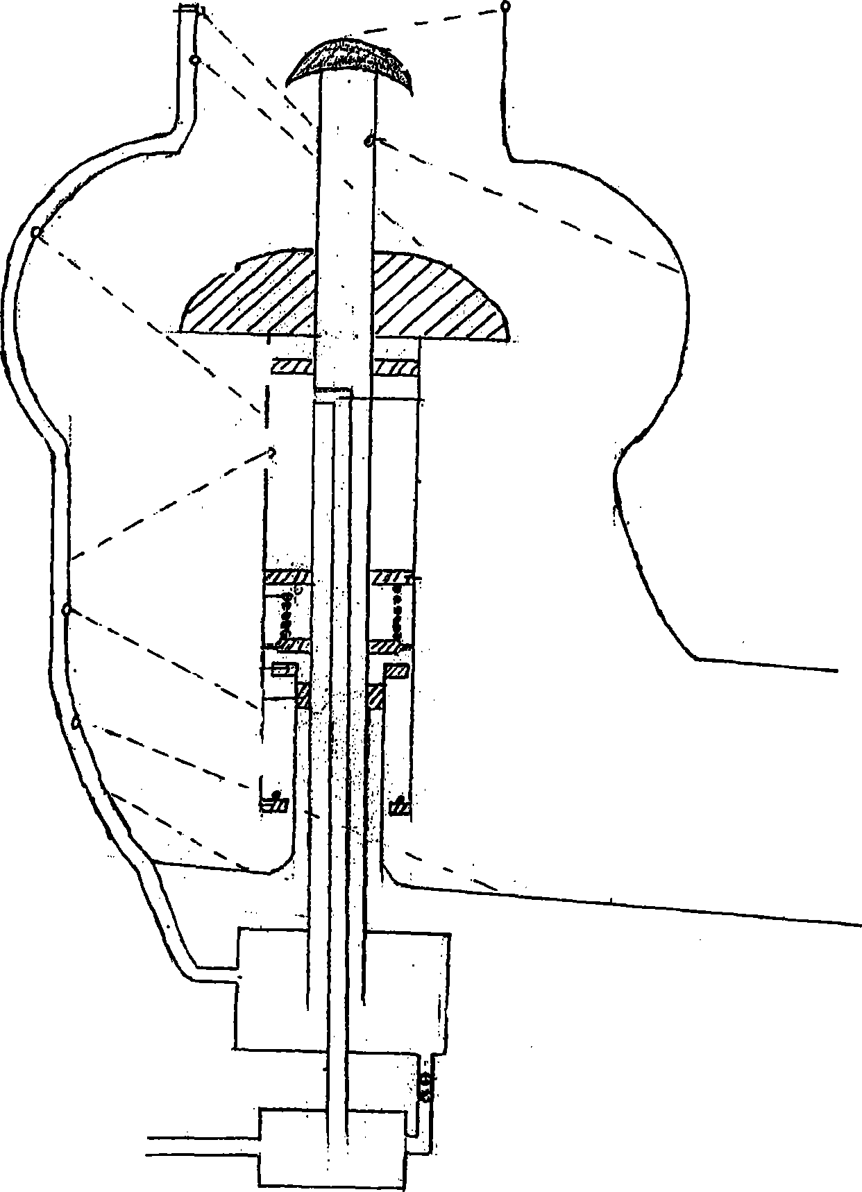
Figure 2 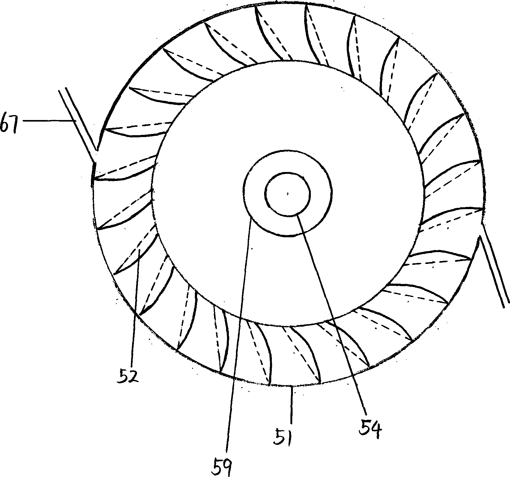
Figure 3
Abstract
Description
technical field
[0001] The present invention relates to the technical field of water-saving toilet applications, especially the domestic patent application with the patent application number of 201210322706.0 and the PCT patent application with the patent number of PCT / CN2013 / 001035. In addition, it also involves several unpublished patent applications applied by the applicant. patent application. Background technique
[0002] Most of the closets at present, except the novel closet that I apply for, hardly relate to the device technical scheme of the present invention. Compared with the technology of the present invention, the partial water flow control technology of toilet rotation and flushing proposed by me has the disadvantage of waste of flushing potential energy. Contents of the invention
[0003] The invention mainly improves the device and scheme of the impeller which drives the rotation of the toilet piston and the water spray shaft tube and its structure, as wel...
Examples
Embodiment Construction
[0017] The type closet introduced for my above-mentioned patent application with the device now, the driving wheel (52) on the water spray shaft pipe of the device is bucket-shaped now, and the water repelling wheel (62) and its pump chamber (64) are DBZ type self-priming Taking the pump structure as an example, the device and design scheme of the present invention are introduced.
[0018] The closet spray shaft pipe (53) is sealed and surrounded by the container (51), the small container (55), the pump chamber (64), and the small container (61) from top to bottom respectively. Simultaneously, small container (55) is in large container (51), and the lower end (63) of large container (51) is also the lower end of small container (55), the upper end of pump chamber (64) simultaneously. The driving wheel (52) on the shaft tube (53) is located at the top of the container (51), and the shaft tube part surrounded by the small container (55) has a water inlet hole (65) on the shaft t...