
Flexible wall supported wiper blade hydraulic wiper
A flexible wall and hydraulic technology, which is applied in vehicle cleaning, vehicle maintenance, transportation and packaging, etc., can solve problems such as difficult quick scraping, wiper motor burnout, large transmission torque, etc., to achieve rapid response and scraping efficiency Improves and transmits the effect of large torque
Patent Information
- Authority / Receiving Office
- CN · China
- Patent Type
- Patents(China)
- Current Assignee / Owner
- Publication Date
- 2016-05-25
Smart Images
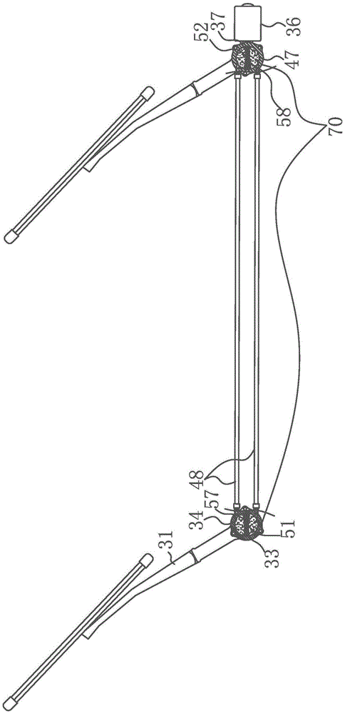
Figure 1 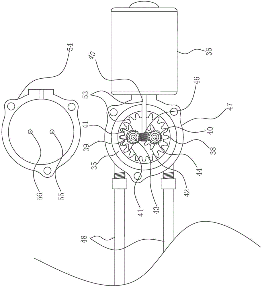
Figure 2 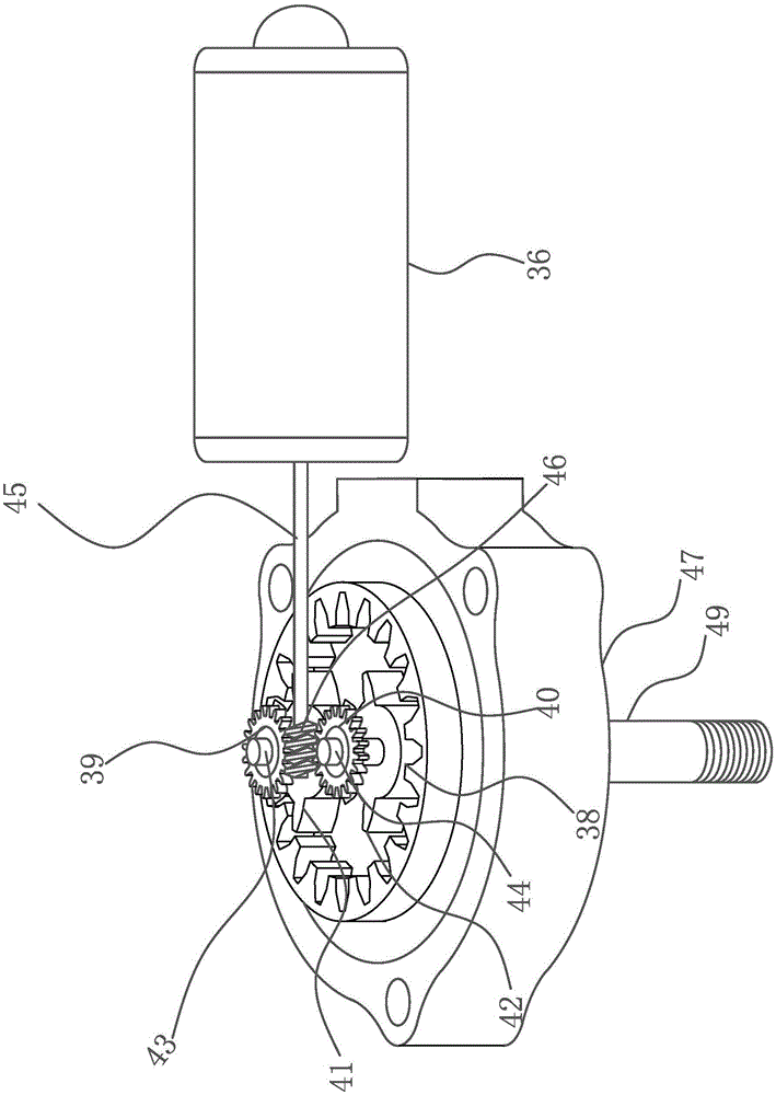
Figure 3
Abstract
Description
Technical field
[0001] The invention relates to a wiper, which belongs to the field of automobile wipers, in particular to a hydraulically driven wiper. Background technique
[0002] At present, most of the wiper driving mechanisms of wipers on the market are connecting rod transmission, which makes a lot of noise during operation, and the connecting rod transmission mechanism is open, which is greatly affected by the outside. Cause the wiper motor to burn out; the support platform of the wiper blade on the market is usually rigid, because the windshield glass is a curved surface shape, coupled with manufacturing reasons and wear and tear during use, the surface of the windshield glass is irregular and defective. It is difficult for the wiper under the rigid support to adapt to the change of the surface of the windshield. During the scraping process, the wiping efficiency is low, it is not easy to scrape quickly, and it is easy to cause blurred vision and bring safety hazard...
Examples
Embodiment Construction
[0017] Figure 1-Figure 7 In the embodiment, a flexible wall supports the wiper blade hydraulic wiper, including the wiper motor 36, the wiper drive mechanism 70 and the wiper 31, and the feature is that the wiper drive shaft 50 is divided into a passive wiper drive shaft 32 and an active wiper drive shaft 49 , and are respectively coaxially connected with the passive cylinder shaft 51 of the passive vane swing cylinder 34 and the active cylinder shaft 52 of the active vane swing cylinder 47; the passive cylinder shaft 51 and the active cylinder shaft 52 are respectively provided with a passive cylinder partition 57 and an active The oil cylinder partition 58, the passive blade swing oil cylinder 34 and the active blade swing oil cylinder 47 communicate and transmit torque through the hydraulic oil pipe 48; the active blade swing oil cylinder 47 is provided with a forward and reverse gear intermittent transmission mechanism 53, and its structure is: The axial side of the activ...