
A two-stage compressor
A two-stage compressor, one-stage technology, applied in the direction of mechanical equipment, machine/engine, pump combination for elastic fluid rotary piston type/oscillating piston type, etc., can solve the problem of insufficient air intake of high-pressure stage cylinders, compressors Problems such as limited displacement and reduced performance of the compressor achieve the effect of keeping the suction and exhaust process smooth and avoiding pulsation
Patent Information
- Authority / Receiving Office
- CN · China
- Patent Type
- Patents(China)
- Current Assignee / Owner
- Publication Date
- 2017-02-15
Smart Images
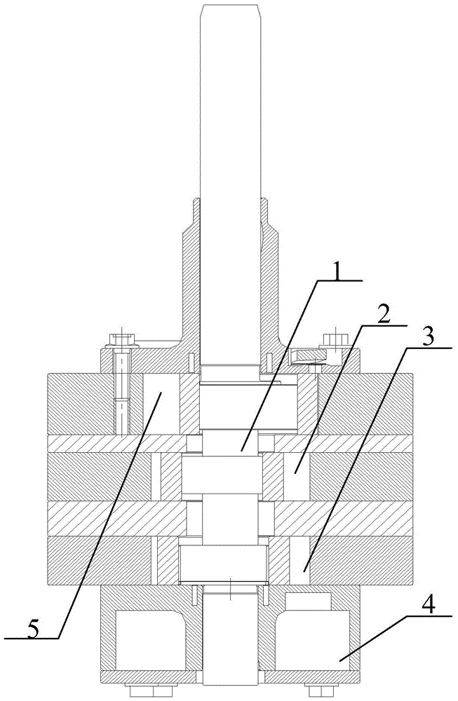
Figure 1 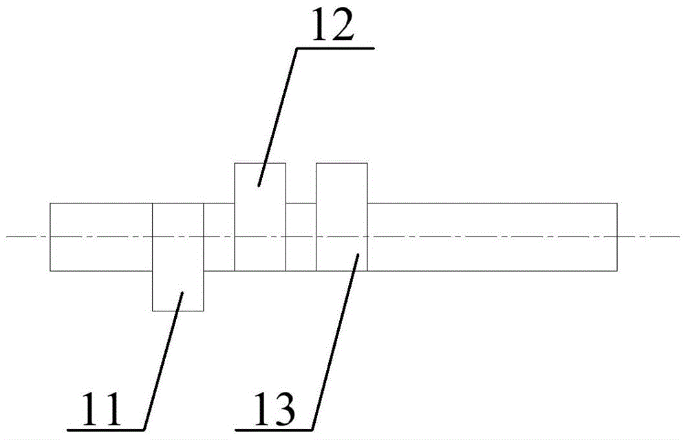
Figure 2 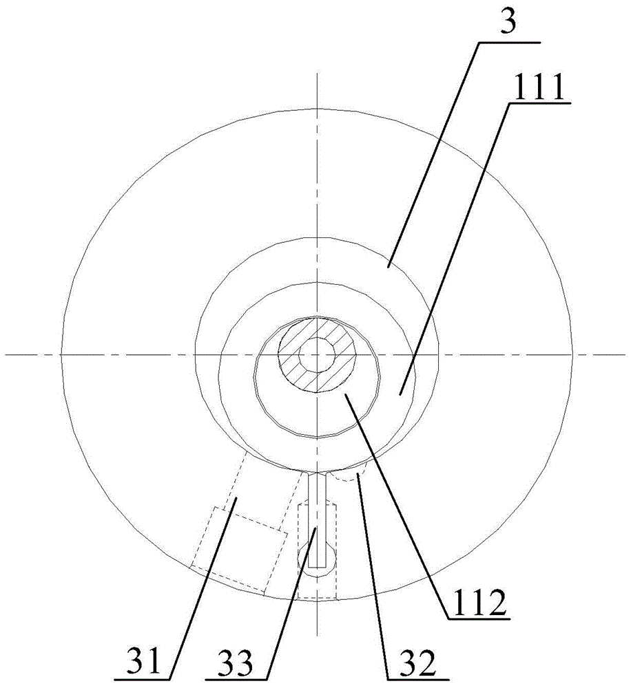
Figure 3
Abstract
Description
technical field
[0001] The invention relates to the technical field of preparation of air-conditioning compressors, in particular to a multi-cylinder two-stage compressor. Background technique
[0002] The current rolling rotor two-stage compressor generally includes a low-pressure stage cylinder and a high-pressure stage cylinder. The low-pressure stage cylinder forms a stage of compressed gas after completing the stage of compression. The compressed gas undergoes secondary compression to form a secondary compressed gas.
[0003] Since the low-pressure cylinder and high-pressure cylinder of the current two-stage compression cylinder only contain one cylinder, the displacement of the entire compressor is relatively limited, which is increasingly unable to meet the use environment of large-scale temperature regulation, and the current two-stage compression cylinder The suction connection between the middle and low-pressure cylinders and the high-pressure cylinders is not rea...
Examples
Embodiment 1
[0048] Please refer to Figure 1 to Figure 5 , figure 1 It is a partial cross-sectional schematic diagram of a two-stage compressor, figure 2 It is a structural schematic diagram of the crankshaft in the first embodiment, image 3 is a schematic top view of the first cylinder in the first embodiment, Figure 4 It is a schematic top view of the second cylinder in the first embodiment, Figure 5 It is a schematic plan view of the high-pressure stage cylinder in the first embodiment.
[0049] In the embodiment of the present invention, for convenience of description, the eccentric portion in the first eccentric assembly 11 in the first cylinder 3 is named as the first eccentric portion 112, and the eccentric portion in the second eccentric assembly 12 in the second cylinder 2 is named The eccentric part is named the second eccentric part 122, and the eccentric part in the high-pressure eccentric assembly 13 in the high-pressure stage cylinder 5 is named the high-pressure ecc...
Embodiment 2
[0053] Such as Figure 6 As shown in , taking the first eccentric part 112 as a reference, the included angle between the second eccentric part 122 and the first eccentric part 112 is 180°, and the included angle between the high-voltage eccentric part 132 and the second eccentric part 122 is 180° °. It should be noted that the top view diagram of the first cylinder 3 and the top view diagram of the second cylinder 2 in this embodiment are the same as those in Embodiment 1, so please refer to the top view diagram of the first cylinder 3 in this embodiment image 3 , please refer to the schematic diagram of the top view of the second cylinder 2 Figure 4 .
[0054] Please also refer to Figure 7 , Figure 7 It is a schematic plan view of the high-pressure stage cylinder in the second embodiment. Because the angle between the second eccentric part 122 and the first eccentric part 112 is 180°, in order to ensure the timing of the first cylinder 3 and the second cylinder 2 air...
Embodiment 3
[0057] Such as Figure 8 As shown in , taking the first eccentric part 112 as a reference, the included angle between the second eccentric part 122 and the first eccentric part 112 is 0°, and the included angle between the high-voltage eccentric part 132 and the first eccentric part 112 is 180° °. It should be noted that the top view schematic diagram of the first cylinder 3 in this embodiment is the same as that in Embodiment 1, and the top view schematic diagram of the high-pressure stage cylinder 5 is the same as that in Embodiment 1, so the first cylinder 3 in this embodiment Please refer to the top view diagram image 3 , please refer to Figure 5 .
[0058] Please also refer to Figure 9 , Figure 9It is a schematic plan view of the second cylinder in the third embodiment. Since the angle between the second eccentric part 122 and the first eccentric part 112 is 0°, in order to ensure the timing of the intake start of the first cylinder 3 and the second cylinder 2 T...