
Novel automated chair back pressure resistance and fatigue resistance testing device and testing method thereof
A testing device and fatigue technology, which are applied in the field of new automatic seatback compression resistance and fatigue testing device, which can solve the limitation of chair model, lack of seatback compression testing equipment, inability to guarantee stability and accuracy, etc. problem, to achieve the effect of high stability, accurate and reliable test results, and firm and reliable chair fixation
Patent Information
- Authority / Receiving Office
- CN · China
- Current Assignee / Owner
- Publication Date
- 2015-05-27
Smart Images
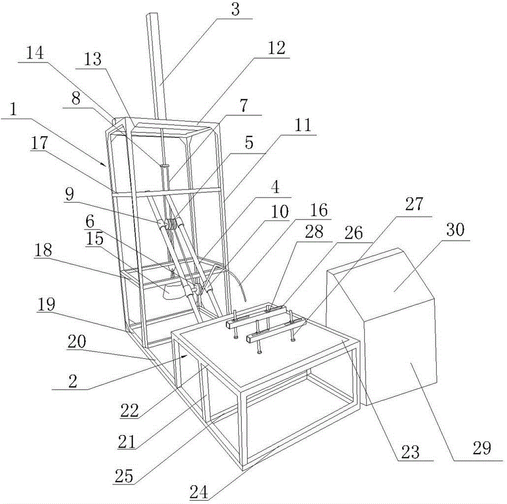
Figure 1 
Figure 2
Abstract
Description
technical field
[0001] The invention belongs to the field of chair quality detection, in particular to a novel automatic chair back pressure resistance and fatigue test device and a test method thereof. Background technique
[0002] During the normal use of the seat, the back of the seat will be subjected to cumulative load and impact force, so a safe and reliable seat must be able to withstand a certain amount of compression and fatigue tests.
[0003] However, existing seat manufacturers generally lack special seat back compression test equipment, and usually use temporary test equipment for testing. This kind of temporary test equipment is generally relatively simple, so that the stability and accuracy in the test process The degree is not guaranteed, and the applicable chair models are also limited. Contents of the invention
[0004] In order to solve the defects and deficiencies in the above-mentioned prior art, the present invention provides a new type of automatic ...
Examples
Embodiment Construction
[0034] The present invention will be described in further detail below in conjunction with the accompanying drawings and embodiments, but it is not intended to limit the protection scope of the present invention.
[0035] like figure 1 and 2 As shown, a new type of automatic chair back pressure resistance and fatigue testing device includes a support bracket 2, a tension bracket 1, a control cabinet 29 arranged on the tension bracket 1 to control the action of the tension mechanism,
[0036] The tension bracket 1 includes four first columns 11 and four support frames arranged between the four first columns 11,
[0037] Tightening mechanism comprises the tensioning cylinder 3 that is arranged on the top of tensioning support 1, the counterweight 15 that is connected on the tensioning cylinder 3 piston rods, two tensioning support rods 4 that are arranged on one side of counterweight 15 and setting On the upper tension wheel 5 and the lower tension wheel 6 between the two tens...