
Farmland irrigation wire and hose winder
A technology of farmland irrigation and pipe reel, which is applied in the field of farmland irrigation reeling machine, can solve problems such as unfavorable handling, storage, unfavorable next use, and irregular collection, and achieves good popularization and application value, saves money, and quickly The effect of conversion
Patent Information
- Authority / Receiving Office
- CN · China
- Patent Type
- Applications(China)
- Current Assignee / Owner
- Publication Date
- 2015-07-15
- Estimated Expiration
- Not applicable · inactive patent
Smart Images
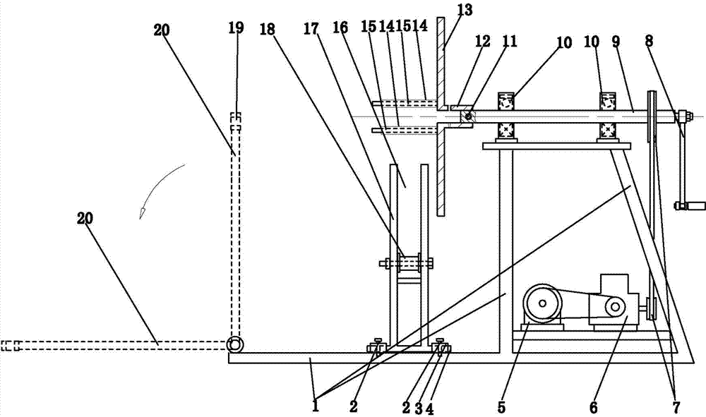
Figure 1 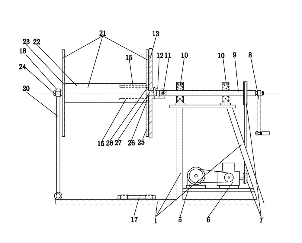
Figure 2 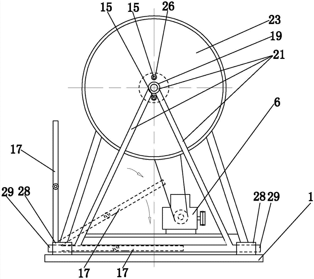
Figure 3
Abstract
Description
technical field
[0001] The invention relates to the field of agricultural drought-resistant irrigation machinery, in particular to a farmland irrigation wire coiling machine. Background technique
[0002] In the vast rural areas of our country, whenever there is a dry season, it is very laborious and troublesome for farmers to irrigate against drought. Watering the ground requires hoses, wires, etc. Sometimes because the land is larger, longer wires and longer hoses are needed. Especially after pouring the ground, it is necessary to tidy up the wires and hoses. The wires are often scattered and entangled during the collection or storage process, which is not conducive to the next use; There is still water in the hose, which is very heavy. In the past, people had to raise the hose while tidying it up to drain the water remaining in the hose. As a rule, it cannot be rolled into a round bundle or disc shape, and it is not used for handling and storage. In addition, when stor...
Examples
Embodiment Construction
[0022] Such as figure 1 , figure 2 As shown, the present invention mainly includes a turntable 13, a rotating shaft 9, a base frame 1, and a power unit. The turntable 13 is set upright, and the rotating shaft 9 is horizontally arranged on the upper part of the base frame 1 through a pair of bearings 10. The right end surface of the turntable 13 is fixedly provided with a connecting sleeve. Tube 12, one end of the rotating shaft 9 penetrates the connecting sleeve 12, and is connected with the connecting sleeve 12 through the connecting pin 11, the rotating disk 13 and the rotating shaft 9 can also be connected by other means such as a coupling, the power device is a manual crank 8, and the rotating shaft The other end of 9 is connected with bolts between the hand crank 8; perhaps the power unit is a motor 5, and the rotating shaft 9 is connected with the output end of the motor 5 through the reduction transmission gear box 6, the belt drive 7.
[0023] When used as a winding ...