
Rotary spray device
A technology of rotating spray and sleeve shaft, applied in the direction of vehicle exterior cleaning devices, etc., can solve the problems of low production efficiency, overflowing drainage, and high labor intensity.
Patent Information
- Authority / Receiving Office
- CN · China
- Patent Type
- Applications(China)
- Current Assignee / Owner
- Publication Date
- 2015-08-19
Smart Images
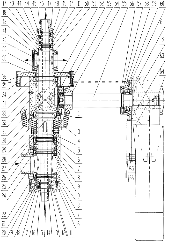
Figure 1
Abstract
Description
technical field
[0001] The invention relates to a cleaning device, in particular to a cleaning device for a cart. Background technique
[0002] The most commonly used tools and utensils in meat food production enterprises are bucket carts (commonly known as meat carts), and standard bucket carts with a volume of 200 liters are the most widely used. The bucket truck is internationally accepted, in the shape of a square bucket, with four casters at the bottom and a handle on the side for easy pushing. The bucket trucks need to be cleaned and disinfected after turning once a week. For a long time, the cleaning of bucket trucks has basically relied on manual labor, that is, the operator holds a high-pressure water gun for washing. The disadvantages of this approach are:
[0003] 1. It must be cleaned manually from multiple angles, which is labor-intensive.
[0004] 2. The cleaning water is directly discharged, and the water consumption is huge.
[0005] 3. Drainage overflow...
Examples
Embodiment Construction
[0026] The technical solution of the present invention is described in detail below. The embodiment of the present invention is only for illustrating a specific structure, and the scale of the structure is not limited by the embodiment.
[0027] see figure 1 , the rotary spraying device of the present invention includes a hollow shaft 15 as an inner ring located at the center of the rotary spraying device, the lower end of which is connected to the water inlet pipeline; the sleeve shaft 43 is located outside the hollow shaft 15 to form a middle ring; The lower part of the sleeve shaft 43 is provided with two round holes, and the upper part of the sleeve shaft 43 is also provided with two round holes; the bearing seat 32 is provided with two bearings 31 to support the sleeve shaft 43; the insert ring 52 with the joint bearing 53 is used The screw is fixed on the bearing seat 32; the inner end of the transmission shaft 55 is in a stepped structure, the main gear 54 is installed...