
A self-adjustable knotting machine
A knotting machine and self-adjusting technology, applied in the field of knotting machines, can solve the problems of inability to perform complex knotting, poor generality of knotting machines, etc., and achieve the effects of high production efficiency, good completion, and reduced production costs.
Patent Information
- Authority / Receiving Office
- CN · China
- Patent Type
- Patents(China)
- Current Assignee / Owner
- Publication Date
- 2017-03-29
- Estimated Expiration
- Not applicable · inactive patent
Smart Images
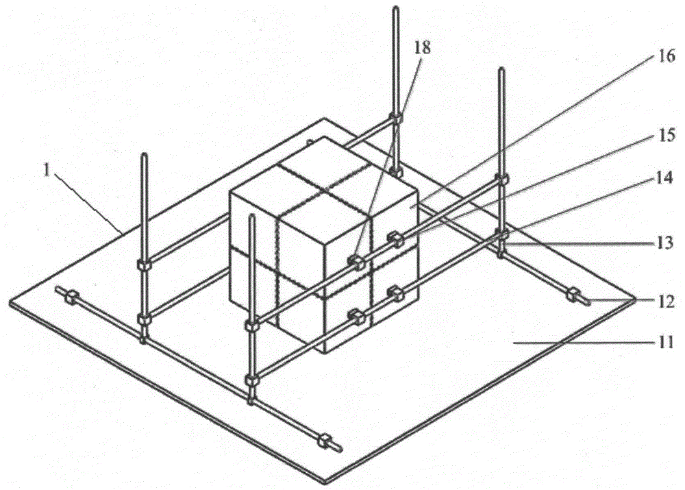
Figure 1 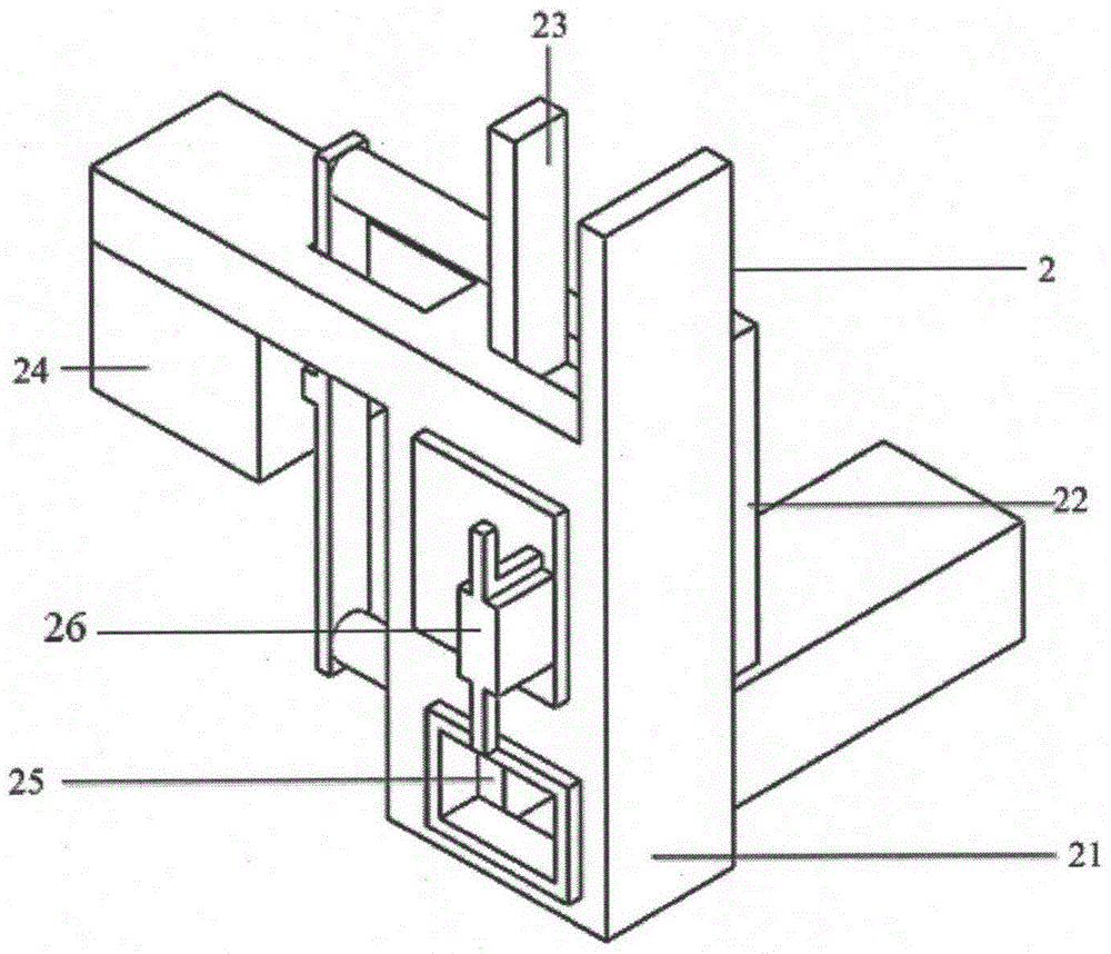
Figure 2 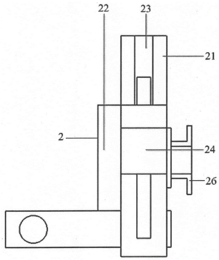
Figure 3
Abstract
Description
technical field
[0001] The invention relates to a knotting machine, in particular to a knotting requirement for different styles of single knotting or double knotting which is applied to textile fibers such as cotton and hemp. The knotting can be realized by adjusting the position of the module A working knotting machine belongs to the technical field of textile equipment. Background technique
[0002] The knotting work occupies an indispensable position in the field of textile and clothing. The traditional knotting method realizes kinks manually, so as to complete the winding of a single thread or multiple threads, which can improve the tensile strength or beautify the decoration. The general knotting machine usually determines the knotting mode and the knotting object at the beginning of the design, and carries out structural design according to the determined knotting principle and knotting method, and cannot be adjusted according to the changing work requirements. And t...
Examples
Embodiment
[0021] Such as Figure 1-9 As shown, the structure diagram of a self-adjustable knotting machine provided by the present invention includes a guide module 1 and a control module 2; wherein the guide module 1 includes a platform 11, a support bar 12, a horizontal slide bar 14, and a vertical slide bar 13. The slider 15, the knotting cavity 16, the air plug 17, the handle 18, the control module 2 includes a support 21, a sensor 22, an upper chuck 23, a cylinder 24, and a lower chuck 25. Two support bars 12 are installed on the platform 11, and two horizontal slide bars 14 are installed on each support bar 12 to enable the knotting chamber 16 to move horizontally. Vertical slide bar 13 can make knotting cavity 16 realize vertical movement, is provided with two slide blocks 15 on every vertical slide bar 13, and slide block 15 cooperates with handle 18, and handle 18 can be bonded on Knotting chamber 16, so as to control the displacement of each slide bar and slider 15 to change ...