
Potato planter intelligent spacing adjustment planting unit
A planter and potato technology, applied in potato planters, planting methods, applications, etc., can solve problems such as troublesome adjustment of plant spacing in potato planters
Patent Information
- Authority / Receiving Office
- CN · China
- Patent Type
- Patents(China)
- Current Assignee / Owner
- Publication Date
- 2016-11-23
Smart Images
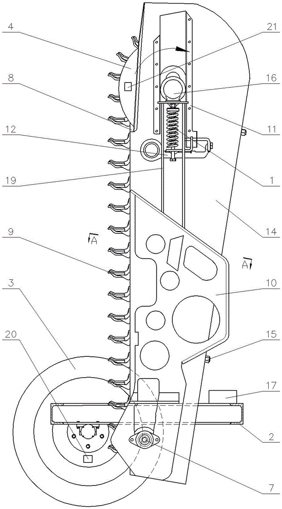
Figure 1 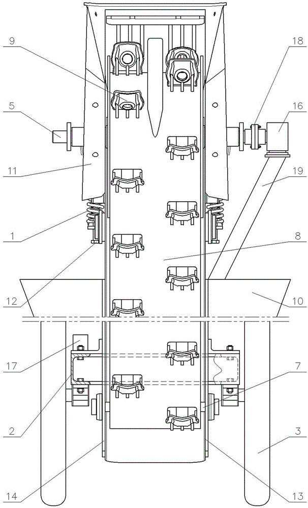
Figure 2 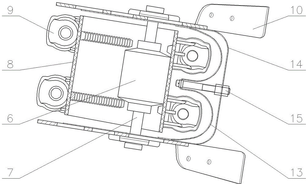
Figure 3
Abstract
Description
technical field
[0001] The invention provides an intelligent plant spacing adjustment sowing unit of a potato planter, which is mainly used in the potato planter. Background technique
[0002] At present, most of the existing potato planting machines fix a simple seed potato bowl on the conveyor chain or conveyor belt. Due to its simple structure, the amplitude of the conveyor chain or conveyor belt cannot be adjusted, and the control of the number of potato seeds in the potato seed bowl is not enough. Precise, it is very easy to cause missed or repeated seeds, which will affect the later growth and development of potatoes. Therefore, Leling Tiancheng Engineering Machinery Co., Ltd. invented a "planting device for bowl and spoon seeding of root crops", authorized patent number: ZL2012200930666. However, it has been found through tests and practical applications that the plant spacing of the potato seeder involved in this patented technology is not easy to adjust, and it is ...
Examples
Embodiment Construction
[0013] 1. Tensioning device 2, frame 3, ground wheel 4, driving roller 5, driving shaft 6, driven roller 7, driven shaft 8, conveyor belt 9, potato seed bowl 10, bracket I 11, slideway 12, Bracket II 13, guide tube 14, shield 15, gap adjustment device 16, hydraulic motor 17, controller 18, coupling 19, bracket III 20, sensor I 21, sensor II.
[0014] exist Figure 1~3 In the shown embodiment: the driving shaft 5 arranged horizontally is located above the driven shaft 7, and the driven shaft 7 is parallel to the driving shaft 5; the two ends of the driven shaft 7 with the driven roller 6 fixed in the middle are supported on the bracket I10 , the two ends of the driving shaft 5 with the driving roller 4 fixed in the middle are located in the slideway 11 arranged in the vertical direction, and the driving shaft 5 is supported on the bracket II 12 located at the two ends of the driving shaft 5 through the tensioning device 1, the driving roller 4 and The same conveyer belt 8 is h...