
A high-speed quality inspection machine using machine vision inspection
A technology of machine vision inspection and quality inspection machine, which is applied in the direction of instruments, measuring devices, scientific instruments, etc. It can solve the problems of inability to meet the needs of automated production and low efficiency of manual inspection, shorten the focusing time, facilitate clear imaging, and improve yield. The effect of volume speed
Patent Information
- Authority / Receiving Office
- CN · China
- Patent Type
- Patents(China)
- Current Assignee / Owner
- Publication Date
- 2018-03-02
Smart Images
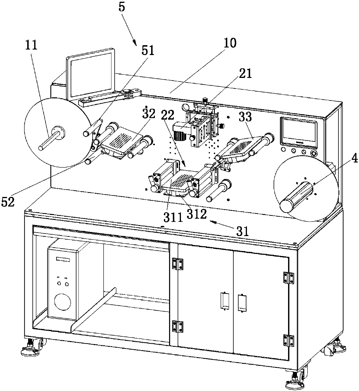
Figure 1 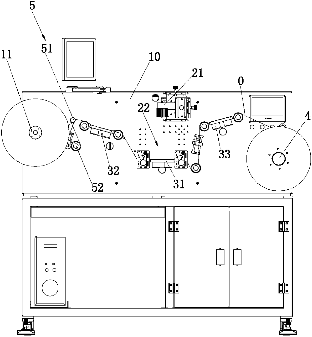
Figure 2 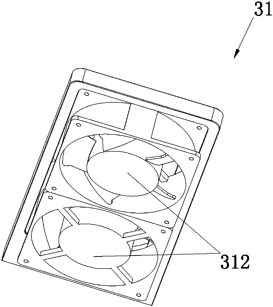
Figure 3
Abstract
Description
technical field
[0001] The invention relates to the technical field of detection equipment, in particular to a high-speed quality inspection machine using machine vision detection. Background technique
[0002] In industries such as mobile phones and electronic products, it is often necessary to paste labels, barcodes, QR codes, etc. on products. With the emergence of automatic labeling equipment, the efficiency of labeling has been greatly improved, but there are new requirements for the accuracy of the information to be labeled, so it is necessary to detect the labels to be labeled. Manual inspection is inefficient and cannot meet the needs of automated production.
[0003] Therefore, it is necessary to provide a device for automatic and rapid detection of labels, barcodes and two-dimensional codes. Contents of the invention
[0004] The purpose of the present invention is to provide a high-speed quality inspection machine using machine vision detection, which has high...
Examples
Embodiment 1
[0039] like figure 1 , 2 As shown, a high-speed quality inspection machine utilizing machine vision detection according to the present invention includes a base frame assembly 10 and an imaging lens 21, and the imaging lens 21 is arranged on the base frame assembly 10, and also includes an imaging station 22 for supporting coil materials The material roll 11, the first material tape suction station 31 and the material receiving roller 4, the imaging lens 21 is arranged on one side of the imaging station 22, and the first material tape suction station 31 is arranged on the other side of the imaging station 22 On the other hand, the winding roller 11 is arranged at one end of the base frame assembly 10 , and the receiving roller 4 is arranged at the other end of the base frame assembly 10 . The code to be detected is attached to the bottom film to form a tape 0, which is wound into a roll and placed on the coil roll 11, and the take-up roll 4 rotates under the drive of an exter...
Embodiment 2
[0049] like figure 1 , 2 , 6, the difference between this embodiment and the first embodiment is that the swing arm assembly 54 includes a long arm 541 and a short arm 542, one end of the short arm 542 is rotatably arranged on the base assembly 10, and the brake band 55 One end of the short arm 542 is fixed to one end of the short arm 542, the other end of the short arm 542 is close to the long arm 541, the pendulum roller 51 is rotatably arranged on one end of the long arm 541, and the other end of the long arm 541 is rotatably arranged on the base frame assembly 10 And arranged between the short arm 542 and the winding roller 11 . When the material belt 0 is pulled by the traction device, under the action of the material belt 0, the long arm 541 swings, and the long arm 541 pushes the short arm 542 to swing, and one end of the short arm 542 loosens the braking band 55, and the winding roller 11 Losing the function of the braking band 55, the winding roller 11 rotates under...