
External Prestressed Strengthening Structure and Method of Concrete T Beam
A technology of external prestressing and strengthening structures, which is applied in bridge reinforcement, bridges, bridge materials, etc., can solve the problems of reducing the durability of steel strands, expensive FRP bars, and complicated construction processes, so as to improve bearing capacity and durability , good reinforcement effect and convenient construction
Patent Information
- Authority / Receiving Office
- CN · China
- Patent Type
- Patents(China)
- Current Assignee / Owner
- Publication Date
- 2018-06-29
Smart Images
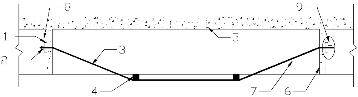
Figure 1 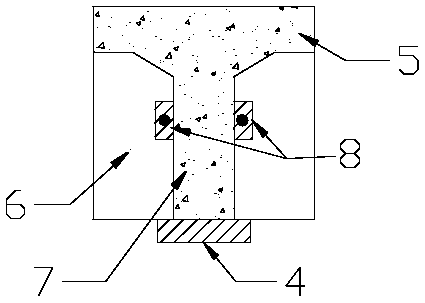
Figure 2 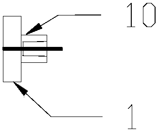
Figure 3
Abstract
Description
Technical field
[0001] The invention relates to the field of concrete construction, in particular to an external prestressed reinforcement structure and method of a concrete T-beam.
Background technique
[0002] T-beams are widely used in concrete bridge structures due to their characteristics. In the existing bridge structure, the structure or components are often seriously damaged due to design errors, construction errors, and material quality not meeting the requirements; or due to increased structural loads, changes in use functions, and force majeure factors such as earthquakes and fires. , the demand for reinforcement of concrete T-beams is increasing. Among them, external prestressed reinforcement has been widely used in practical engineering because of its own advantages of high efficiency, economy and simple construction.
[0003] At present, when external prestressing is performed on concrete T-beams, most of the materials used are steel strands, and prestres...
Examples
Embodiment Construction
[0029] The present invention will be described in further detail below in conjunction with the accompanying drawings.
[0030] see Figure 1 to Figure 3 The reinforcement structure of the present invention includes several vertical diaphragms 6 arranged side by side on the lower side of the concrete T beam flange 5; the bottom of the concrete T beam web 7 is provided with a pair of horizontal support pads 4, and each pair of support pads The plates 4 are all located between two adjacent diaphragms 6; one end of the high-strength aluminum alloy rib 3 is respectively fixed on the diaphragm 6, and one end of the high-strength aluminum alloy rib 3 passes through the diaphragm 6 and passes through the end plate 1 and aluminum alloy bolts 2 for anchoring to form the anchor end 8; the other end of the high-strength aluminum alloy bars 3 passes through the diaphragm 6, and through the end backing plate 1 and the wedge-shaped clip-type anchor 10 through the core-type jack Anchored by ...