
A flat-stayed cable bridge with tubular deck
A tubular and steel tube technology, applied in the field of tubular deck flat-stayed cable bridges, can solve problems such as adverse effects of anti-corrosion treatment on the environment, limiting the popularization and application of flat-stayed cable bridges, poor durability of wooden structures, and reducing maintenance workload. and cost, improve driving stability and safety, and prolong service life
Patent Information
- Authority / Receiving Office
- CN · China
- Patent Type
- Patents(China)
- Current Assignee / Owner
- Publication Date
- 2017-10-27
Smart Images
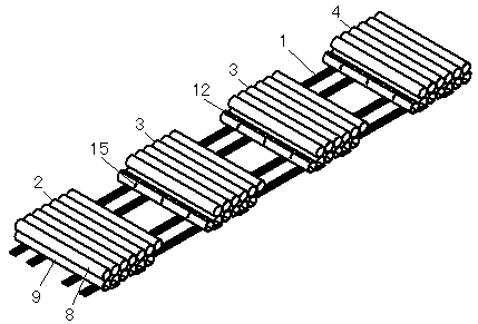
Figure 1 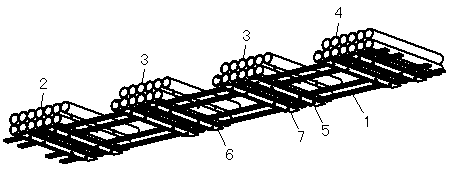
Figure 2 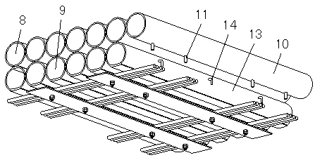
Figure 3
Abstract
Description
technical field
[0001] The invention relates to a flat-stayed cable bridge with a tubular deck, belonging to the technical field of bridge structures. Background technique
[0002] Flat-stayed cable bridge is a flexible bridge system with steel cables as the force-bearing structure, the bridge deck is directly laid on the steel cables, and the line shape of the bridge deck is basically consistent with the line shape of the steel cables. Therefore, in order to adapt to the deformation of the cables, the deck of the cable-stayed bridge is usually spliced longitudinally by smaller decks. The bridge deck of the existing flat-stayed cable bridge generally adopts a wooden structure, for example, the "deck structure of a flat-stayed cable bridge" disclosed by the applicant in the patent document with publication number 202989775U. Due to the low strength of the wooden structure, a thicker bridge deck is required to bear the larger vehicle load, so the requirements for the materi...
Examples
Embodiment 1
[0025] This example Figure 1 to Figure 8As shown, it consists of a number of standard steel pipes and special-shaped steel pipes juxtaposed. The standard steel pipe is used as the upper steel pipe 8, and the special-shaped steel pipe is used as the lower steel pipe 9. A number of standard steel pipes are welded side by side to form a plane as the bridge deck, that is, the centers of all standard steel pipes are located on a straight line when viewed from the cross section. The special-shaped steel pipe is connected with the steel cable 1. There are two types of special-shaped steel pipes, one is located on the edge of the component and needs to be connected with adjacent components, such as the protruding steel tube 17 in the lower layer and the extra steel tube 18 in the lower layer, and the other is located in the middle of the component and does not need to be connected to adjacent components The rest of the lower steel pipes 9 connected by the components. All the other...
Embodiment 2
[0028] This example Figure 1 to Figure 8 As shown, all the staples 11 in the embodiment are replaced with hooks 14, and all the staple holes 12 are replaced with hook holes 15 to form the second embodiment. Since the shape of the hook 14 is different from that of the staple 11, the shape of the corresponding hook hole 15 should also correspond to it.
Embodiment 3
[0030] The connector in embodiment 1 is a staple 11 , and the connector in embodiment 2 is a hook 14 . In practice, the two connectors can also be used at the same time, which can be used as embodiment 3.