
A smelting short net
A short network and main row technology, applied in the field of ore smelting, can solve the problems of large power consumption, power waste, low utilization efficiency of transformers, etc., and achieve the effect of reducing reactance
Patent Information
- Authority / Receiving Office
- CN · China
- Patent Type
- Patents(China)
- Current Assignee / Owner
- Publication Date
- 2022-06-21
Smart Images
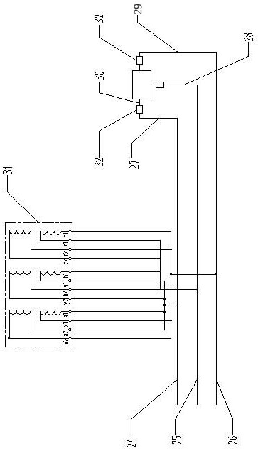
Figure 1 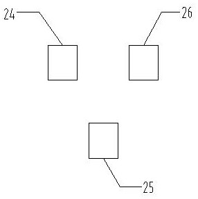
Figure 2 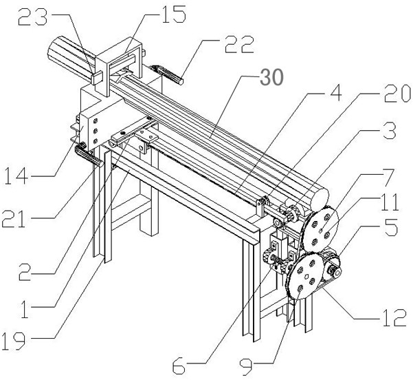
Figure 3
Abstract
Description
technical field
[0001] The invention relates to the field of ore smelting, in particular to a smelting short net. Background technique
[0002] Pearl sand has been recognized by the foundry industry as a precision casting material, and its usage is gradually increasing. The principle is to connect an electrode rod through three main rows through high-voltage three-phase electricity, and then generate an arc through the electrode rods on the three main rows approaching each other. Heat is released, and the production of orb sand is carried out by the heat generated.
[0003] Electricity is the main cost in the production process of pearl sand. In the prior art, three main rows are arranged in parallel on the same plane. Due to the large current passing through the main rows, "enhanced phase" and "weakened phase" are generated between the three main rows. Lead to power transfer; the positions of the three electrode rods are relatively fixed, and the current in the three main ...
Examples
Embodiment Construction
[0023] like Figure 1 to Figure 6 As shown, a short smelting net includes a first main row 24, a second main row 25, a third main row 26, and a corresponding connection with the first main row 24, the second main row 25, and the third main row 26 respectively. The first branch row 27 , the second branch row 28 and the third branch row 29 are provided with electrode rods 30 on the first branch row 27 , the second branch row 28 and the third branch row 29 . The first main row 24 , the second main row 25 and the third main row 26 are arranged parallel to each other, the second main row 25 is located below the first main row 24 and the third main row 26 and the first main row 24, the second main row 25 and the third main row The distances between the rows 26 are equal to each other; the first row 27, the second row 28 and the third row 29 are respectively connected with the electrode rod 30 through the electrode pushing device 32; the electrode pushing device 32 includes a linear ...