
An electronic lock box with mechanical interlock function
A technology of mechanical interlocking and electronic locking, which is applied to coin accepting devices, instruments, and handling coins or valuable banknotes, etc., which can solve the problems of inconvenient background management, plug-in board insertion, confusion of counting times of taking out, misunderstanding, etc., and achieve simplification Time and efficiency, the effect of accurate data upload
Patent Information
- Authority / Receiving Office
- CN · China
- Patent Type
- Patents(China)
- Current Assignee / Owner
- Publication Date
- 2022-04-08
Smart Images
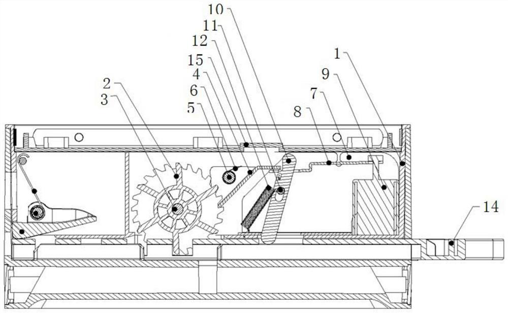
Figure 1 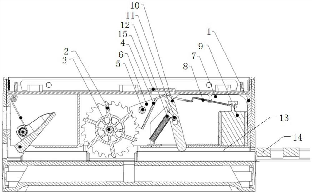
Figure 2
Abstract
Description
technical field
[0001] The invention relates to the technical field of coin slot machine electronic cash register, in particular to an electronic lock box with a mechanical interlock function. Background technique
[0002] Every year, the bus company loses a large amount of fares due to the poor anti-theft performance of the coin-operated gate box. Due to the large changes in the time and location of the bus cash register, and the large number of personnel in the collection process, it is difficult to investigate and deal with the loss of fares without evidence. . In the prior art, in order to improve the anti-theft capability of the ticket, the insertion and removal time of the cassette plate are usually counted.
[0003] However, the existing electronic cassette needs to continuously supply power to the valve electromagnet when the plug board is pulled out, otherwise the cassette board will be locked during the pulling out process. When the valve electromagnet is restart...
Examples
Embodiment Construction
[0020] In order to facilitate those skilled in the art to better understand the essence of the present invention, the specific implementation manners of the present invention will be described in detail below in conjunction with the accompanying drawings.
[0021] Such as figure 1 , figure 2 As shown, an electronic lock box with mechanical interlocking function includes: a liner 1 arranged in the box, a ratchet mechanism, an interlock mechanism, a slot 13, a box plate 14 and a cover plate 15, the box The box lining 1 and the cover plate 15 form a cavity, the ratchet mechanism and the interlock mechanism are installed in the cavity, the slot 13 is located at the lower side of the cavity, and the cassette plate 14 is inserted into the slot 13 Connect with ratchet mechanism and interlock mechanism.
[0022] Wherein, the ratchet mechanism includes: a ratchet 2, a ratchet shaft 3, a ratchet stop block 4, a stop block rotating shaft 5 and a stop block pressure spring 6, and the r...