
Zero leakage hydraulic lock
A technology of hydraulic lock and zero leakage, applied in the field of hydraulic components, can solve the problems of inability to meet the use requirements, low reliability index, damage and other problems
Patent Information
- Authority / Receiving Office
- CN · China
- Patent Type
- Applications(China)
- Current Assignee / Owner
- Publication Date
- 2017-09-19
Smart Images
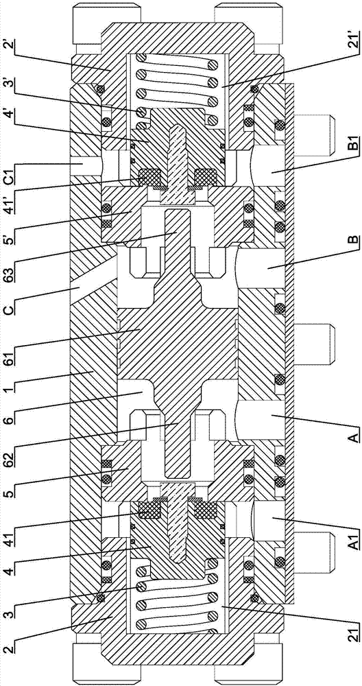
Figure 1 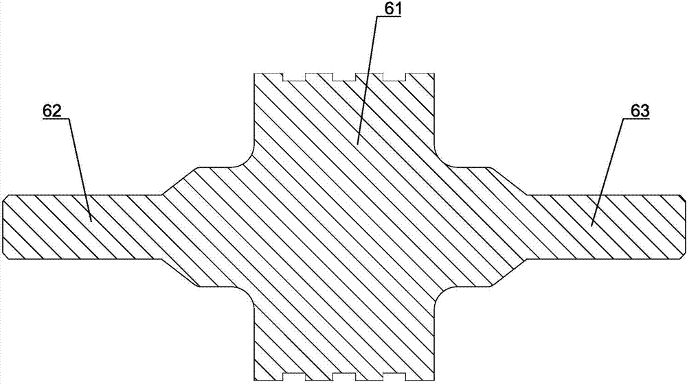
Figure 2 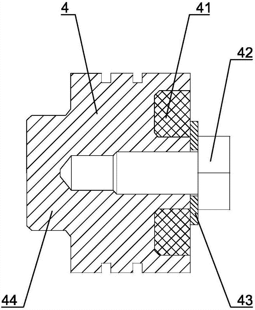
Figure 3
Abstract
Description
technical field
[0001] The invention relates to a hydraulic component, in particular to a zero-leakage hydraulic lock using a soft seal. Background technique
[0002] The hydraulic lock is the key component to realize the locking of the hydraulic system actuator at any position, and it is widely used in the locking circuit. Traditional hydraulic locks adopt hard sealing structures such as cone valves or ball valves, which are difficult to achieve zero leakage and cannot meet the requirements for long-term reliable locking. In order to solve the problems of traditional hydraulic locks, those skilled in the art have developed a hydraulic lock with a soft seal structure in order to achieve zero leakage and reliable locking. However, the reliability index of the hydraulic lock with the existing soft seal structure is low, generally 2000 times. When it is used for about 3000 times, the soft seal pad of non-metallic material will be damaged due to the jet flow phenomenon, which w...
Examples
Embodiment Construction
[0022] First of all, it needs to be explained that the orientation words such as front, back, left, right, up, and down in the present invention are only described according to the accompanying drawings, so as to be easy to understand, and are not intended to describe the technical solutions of the present invention and the scope of protection claimed. limit.
[0023] Such as Figure 1 to Figure 6Shown is a specific embodiment of a zero-leakage hydraulic lock of the present invention, including a cylindrical valve body 1 and a left end cover 2 and a right end cover 2' correspondingly fixed to the left and right ends of the valve body 1. Oil port A, oil port A1, oil port B and oil port B1 are respectively arranged on the valve body 1 . A first groove 21 is provided in the middle of the right end face of the left end cover 2, and a left spring 3 and a left valve 4 are arranged in the first groove 21 from left to right, and a first soft sealing ring 41 is embedded in the right e...