
Monitoring device for a disk brake of a motor vehicle
A disc brake and monitoring device technology, which is applied to the parts of the brake, the type of the brake, mechanical equipment, etc., can solve the problems of inaccurate measurement, high cost, and difficult orientation of the Hall sensor, so as to reduce manufacturing costs and replaceability simplified effect
Patent Information
- Authority / Receiving Office
- CN · China
- Patent Type
- Applications(China)
- Current Assignee / Owner
- Publication Date
- 2018-03-27
Smart Images
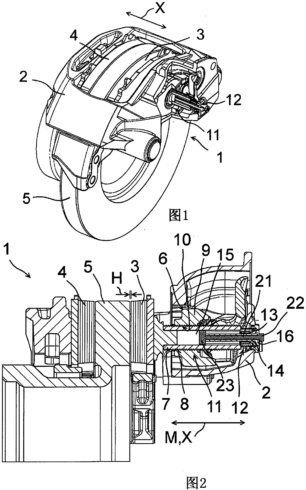
Figure 1 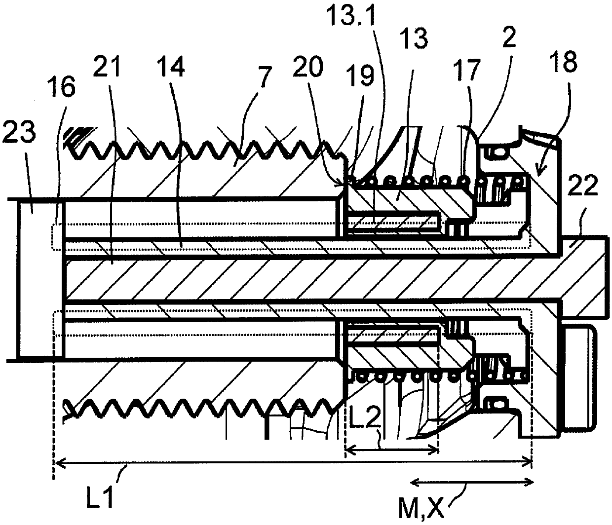
Figure 2 
Figure 3
Abstract
Description
technical field
[0001] The invention relates to a monitoring device for a disk brake for monitoring the relative position of brake linings of the disk brake and to a disk brake, in particular a disk brake for a motor vehicle. Background technique
[0002] Disc brakes in motor vehicles have brake linings which, depending on the actuation of the brake value generator, are pressed by a pressure spindle onto the brake disc connected to the wheel to be decelerated, so that the braking effect can be transmitted onto the brake discs and wheels. Such brake linings are subject to wear when using disc brakes, that is to say their thickness decreases. Thus, the braking travel of the brake lining, that is to say the passage of the brake lining from the released position in which the brake value generator is not actuated to the braking position with the brake value generator actuated The distance is extended in order to achieve the braking effect.
[0003] In order to achieve a fast b...
Examples
Embodiment Construction
[0045] exist figure 1 The disc brake 1 is shown in a perspective view. The disc brake 1 has a brake caliper 2 , brake linings 3 , 4 and a brake disc 5 connected to a wheel to be decelerated, the brake disc being partially surrounded by the brake caliper 2 . The brake linings 3, 4 can be adjusted in the direction of movement X, so that according to a brake value generator, not shown, the brake linings 3, 4 can be pressed against the brake disc 5 in order to induce the desired speed of the wheel to be decelerated. required braking.
[0046] figure 2 A simplified sectional illustration of the disk brake 1 is shown, only relevant sections of the disk brake 1 being shown. In the released position of the disc brake 1 , the brake linings 3 , 4 are spaced apart from the brake disc 5 by the braking travel distance H. The braking stroke H represents the distance traveled by the brake linings 3, 4 from the released position without actuating the brake value generator to the image ...