
Novel new-energy automobile device
A new energy vehicle, a new type of technology, applied in the direction of coupling devices, electric vehicles, electric vehicle charging technology, etc., can solve the problems of charging gun falling off, charging interruption, casualties, etc., and achieve the effect of increasing safety
Patent Information
- Authority / Receiving Office
- CN · China
- Patent Type
- Applications(China)
- Current Assignee / Owner
- Publication Date
- 2018-06-01
- Estimated Expiration
- Not applicable · inactive patent
Smart Images
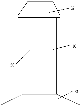
Figure 1 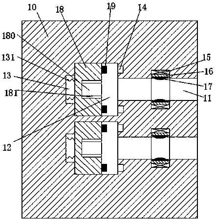
Figure 2 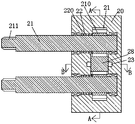
Figure 3
Abstract
Description
technical field
[0001] The invention relates to the field of new energy vehicles, in particular to a novel new energy vehicle device. Background technique
[0002] New energy vehicles are gradually replacing traditional vehicles with many advantages such as energy saving, environmental protection and pollution-free, and are widely used. The charging pile is a supporting facility for new energy vehicles, and it is the carrier for charging new energy vehicles. However, the traditional setting mode of the charging pile is single. Accidentally touching the charging gun or being affected by the pulling of the charging cable may cause the charging gun to fall off, resulting in charging interruption. In addition, traditionally, the conductive sheet in the charging socket is generally set relatively outside. The sheet is easily touched by the metal sheet or metal rod. Therefore, when a person who lacks safety awareness inserts the metal sheet or metal rod into the charging socket, ...
Examples
Embodiment Construction
[0024] All features disclosed in this specification, or steps in all methods or processes disclosed, may be combined in any manner, except for mutually exclusive features and / or steps.
[0025] Any feature disclosed in this specification (including any appended claims, abstract and drawings), unless expressly stated otherwise, may be replaced by alternative features which are equivalent or serve a similar purpose. That is, unless expressly stated otherwise, each feature is one example only of a series of equivalent or similar features.
[0026] like Figure 1 to Figure 8 As shown, a new type of new energy vehicle device of the device of the present invention includes a charging pile body 30 and a charging gun 20 connected to the new energy vehicle. The charging gun 20 is provided with a sliding groove 24 with the notch facing forward, so A sliding bar 28 is slidably installed in the sliding groove 24, and the upper and lower end surfaces of the sliding bar are provided with t...