
Traction winding device for enameled wire
A winding device and enameled wire technology, which are applied in the directions of transportation and packaging, transportation of filamentous materials, and thin material handling, etc., can solve the problems of low winding operation efficiency and inconvenient winding operation of enameled wires.
Patent Information
- Authority / Receiving Office
- CN · China
- Current Assignee / Owner
- Publication Date
- 2018-09-14
- Estimated Expiration
- Not applicable · inactive patent
Smart Images
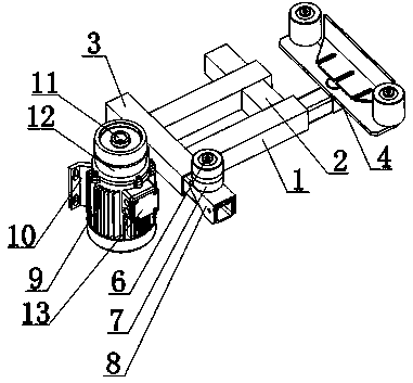
Figure 1 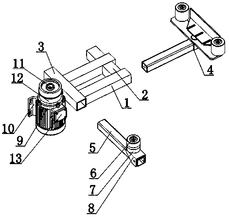
Figure 2 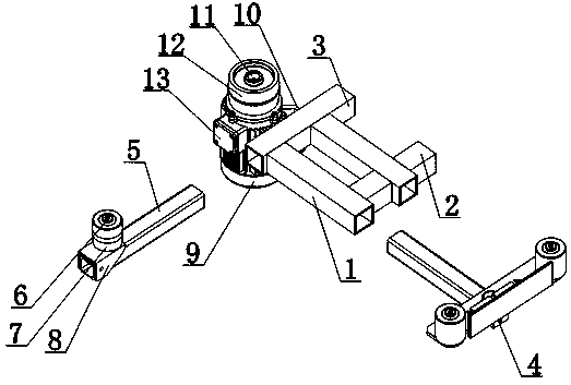
Figure 3
Abstract
Description
technical field
[0001] The invention relates to a pulling and winding device, in particular to an enameled wire pulling and winding device. Background technique
[0002] Enameled wire is a main variety of winding wire, which is composed of two parts: conductor and insulating layer. The bare wire is annealed and softened, and then painted and baked for many times. Performance, chemical performance, electrical performance, thermal performance four major properties. The existing enameled wire is inconvenient to perform winding operation, and the efficiency of rewinding the enameled wire is low. Contents of the invention
[0003] The present invention mainly solves the technical problems existing in the prior art, so as to provide a device that can conveniently move and adjust the traction wheel, and can conveniently rewind the enameled wire through the rewinding wheel; the stepping motor can control the rewinding through the driving shaft. The wheel realizes the rotatio...
Examples
Embodiment Construction
[0018] The preferred embodiments of the present invention will be described in detail below in conjunction with the accompanying drawings, so that the advantages and features of the present invention can be more easily understood by those skilled in the art, so as to define the protection scope of the present invention more clearly.
[0019] Such as Figure 1 to Figure 5 As shown, an enameled wire traction and winding device includes a pair of guide tubes 1, a butt joint tube 2 is provided between one end of the guide tube 1, and an insertion tube 3 is provided between the other ends of the guide tube 1; The part is provided with traction mechanism 4, and the rear portion of plug-in pipe 3 is provided with stepper motor 9, and the top of stepper motor 9 is provided with drive shaft 11, and the outer peripheral surface of drive shaft 11 is set with take-up wheel 12; Traction mechanism 4 includes traction Tube 14, one end of the traction tube 14 is set in the guide tube 1, the o...