
Plug-and-play type ink box control system
A control system, plug-and-play technology, applied in printing, printing devices, etc., can solve the problems of no interlocking security mechanism, data leakage, inability to monitor or monitor the printing process, etc. Effective against illegal attacks and improved security control performance
Patent Information
- Authority / Receiving Office
- CN · China
- Patent Type
- Applications(China)
- Current Assignee / Owner
- Publication Date
- 2018-11-02
- Estimated Expiration
- Not applicable · inactive patent
Smart Images
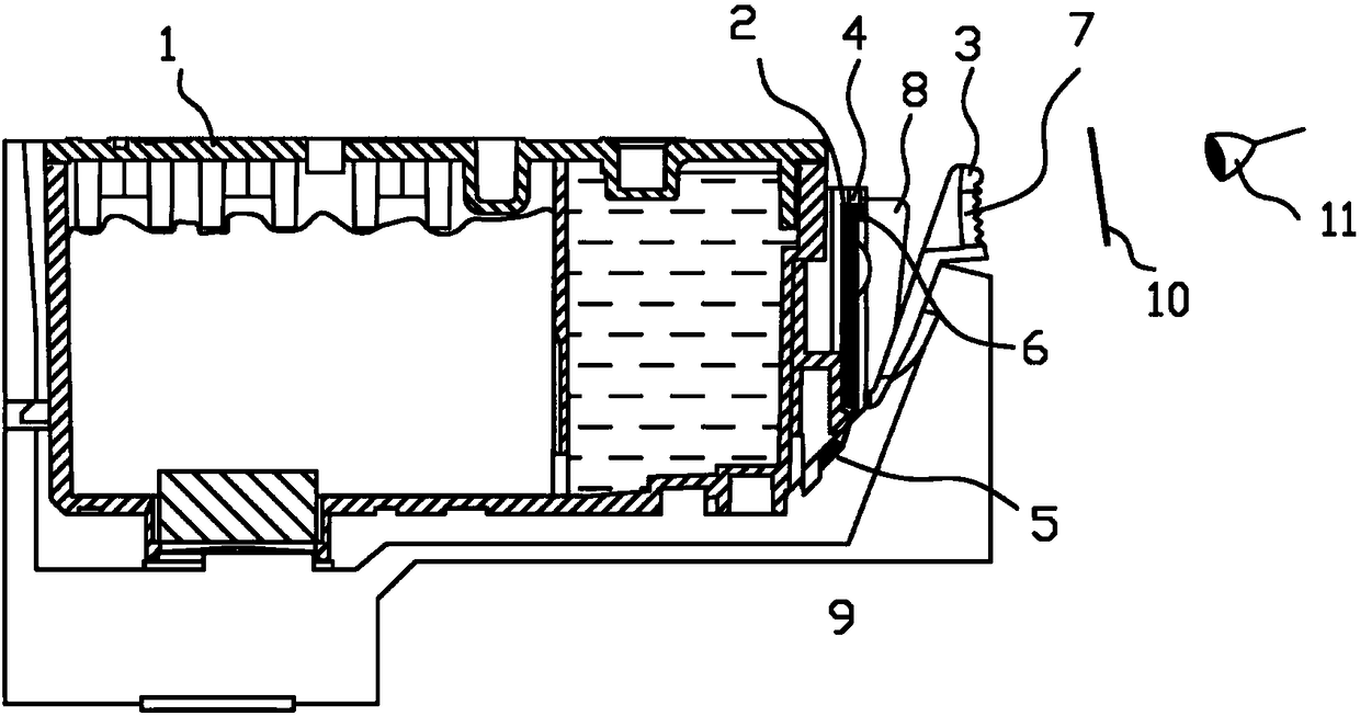
Figure 1 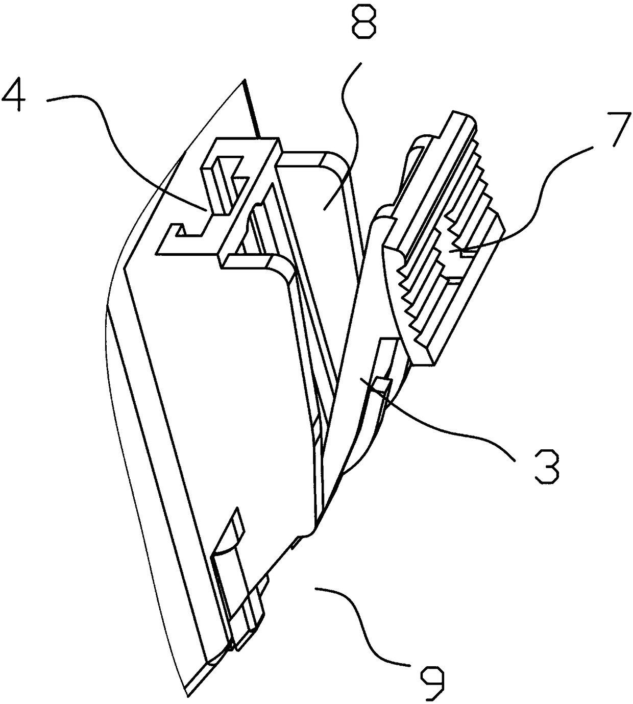
Figure 2
Abstract
Description
technical field
[0001] The invention relates to a printing consumable structure, in particular to a plug-and-play ink cartridge control system. Background technique
[0002] At present, a commonly used printer on the market uses a "light guide column structure" to detect whether the ink cartridge is installed. The principle is to install an identification chip on the ink cartridge, and an optical receiver unit on the side of the printer. After the ink cartridge is installed, the light-emitting unit on the identification chip emits light. The detector unit detects the light emitted by the light guide column, if the light is received, the printer will think that the ink cartridge has been installed; otherwise, the printer will think that the ink cartridge has not been installed.
[0003] When the above detection method is implemented, it must be ensured that the light emitted by the light guide rod received by the light receiver has sufficient
[0004] luminous flux, otherwi...
Examples
Embodiment Construction
[0017] refer to figure 1 , figure 1 The installation structure of the present invention and the printer is shown. During operation, the light emitted by the ink cartridge identification chip passes through the optical filter 10 and is received by the light receiver 11. Once the light receiver 11 receives enough luminous flux to trigger it, the light receiving The trigger is triggered and the printer recognizes the cartridge and starts working normally.
[0018] The printer ink cartridge of the present invention includes an ink cartridge body 1, an identification chip 2 and a chip set on one side of the ink cartridge body 1
[0019] The handle 3, between the ink cartridge body 1 and the handle 3 is provided with a vertical card slot 4, and an exposed card position 5 is provided below the card slot 4, and the upper part of the identification chip 2 is installed in the card slot 4, and the identification chip 2 The lower part extends from the bottom of the card slot 4 and is f...