
Independent compact type expansion joint with inlet and outlet perpendicular to each other
An independent and compact technology, applied in the field of expansion joints, can solve the problems of inability to adapt to different places of use, poor construction flexibility, troublesome installation and disassembly, etc., to achieve easy maintenance or replacement, improve adaptability, and easy installation and disassembly Effect
Patent Information
- Authority / Receiving Office
- CN · China
- Patent Type
- Applications(China)
- Current Assignee / Owner
- Publication Date
- 2018-11-06
Smart Images
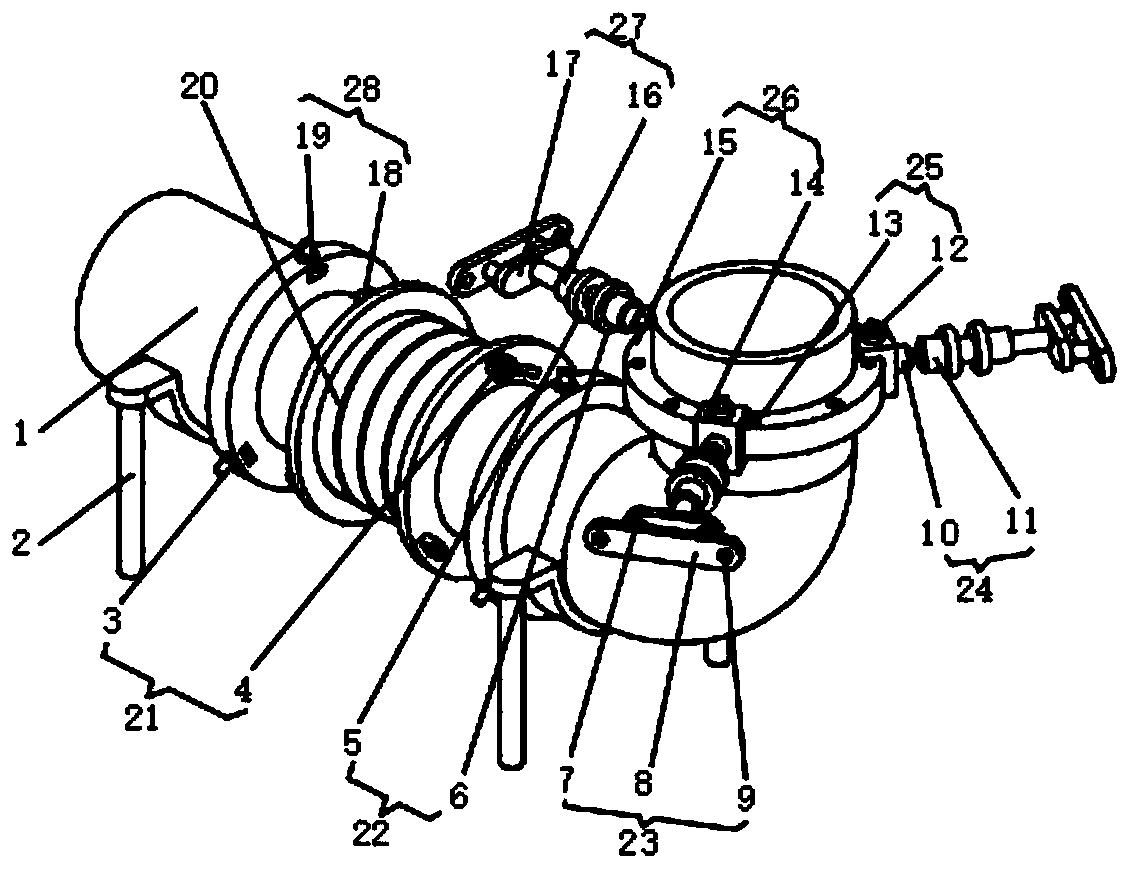
Figure 1
Abstract
Description
technical field
[0001] The invention relates to the technical field of expansion joints, in particular to an independent compact expansion joint with a vertical inlet and outlet. Background technique
[0002] In the prior art: the patent application publication number CN 207195934 U discloses a vertical independent compact expansion joint with an inlet and outlet. The inlet pipe, bellows, elbow and outlet pipe are connected sequentially. The tubes are perpendicular to each other. There are two vertical plates on the outer tube wall of the inlet end tube. Two long rods are connected between the two vertical plates. The long rods extend toward the direction of the bend. There is a cylindrical support body on the board, the bottom of the cylindrical support body is sealed and the top opening is on the support horizontal plate. There is a spring in the cylindrical support body. The spring is connected to the elbow through a support rod. The outer surface of the elbow pipe is wel...
Examples
Embodiment Construction
[0020] The following will clearly and completely describe the technical solutions in the embodiments of the present invention with reference to the accompanying drawings in the embodiments of the present invention. Obviously, the described embodiments are only some, not all, embodiments of the present invention. Based on the embodiments of the present invention, all other embodiments obtained by persons of ordinary skill in the art without making creative efforts belong to the protection scope of the present invention.
[0021] see figure 1 , the present invention provides a technical solution: an independent compact expansion joint with a vertical inlet and outlet, including a delivery pipe 1, the delivery pipe 1 is an L-shaped structure, the inlet end and the outlet end of the delivery pipe 1 are perpendicular to each other, and the delivery pipe 1 The support frame 2 is fixed at the bottom of the transverse tube, and the transverse tube of the conveying pipe 1 is clamped wi...