
Jumping degree-adjustable bionic bouncing device
A bouncing device and large spring technology, applied in the field of robotics, can solve the problems of high weight and energy consumption, low efficiency of obstacle surmounting, low speed and efficiency of legged robots, etc., to achieve the effect of ensuring stability and improving jumping ability
Patent Information
- Authority / Receiving Office
- CN · China
- Current Assignee / Owner
- Publication Date
- 2018-11-30
Smart Images
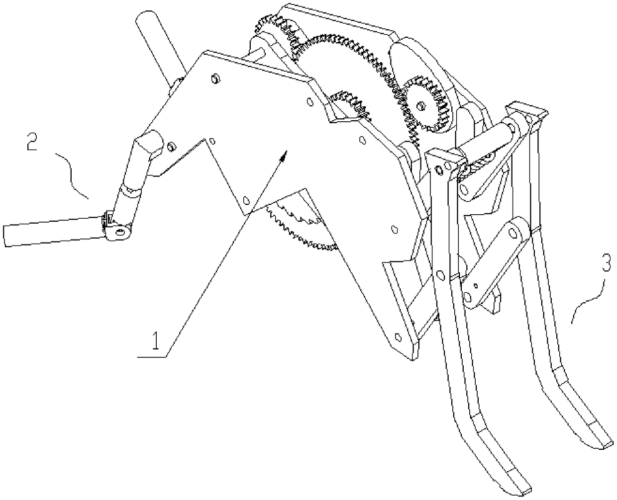
Figure 1 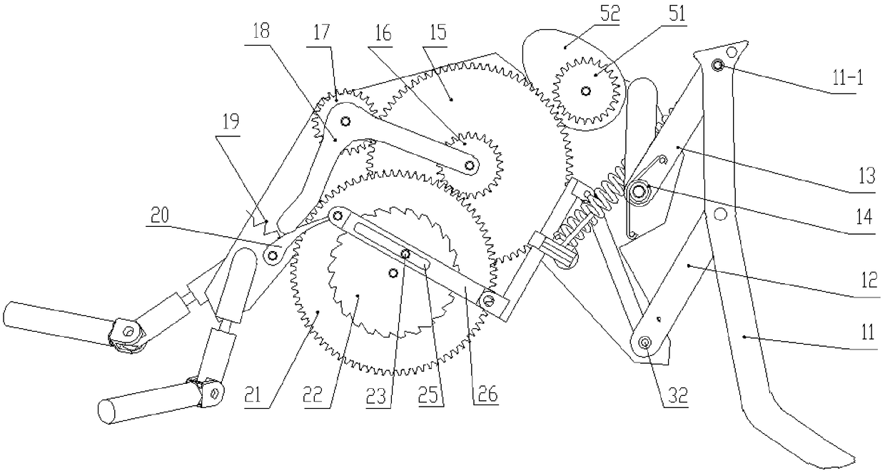
Figure 2 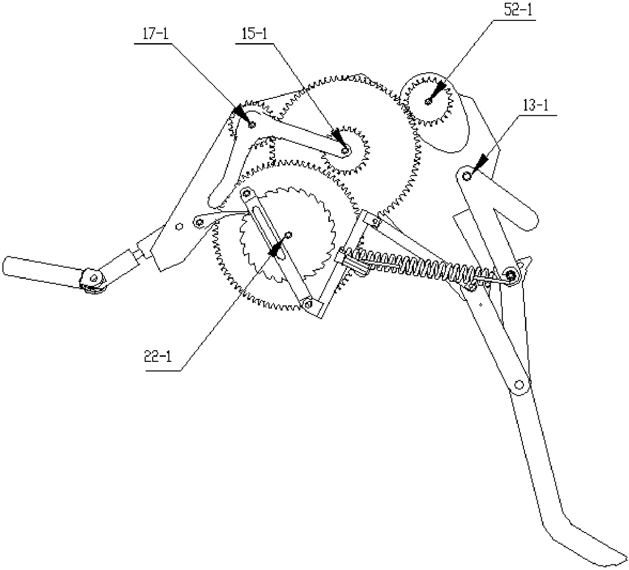
Figure 3
Abstract
Description
technical field
[0001] The invention relates to the technical field of robots, in particular to a bionic bouncing device with adjustable jumping degree. Background technique
[0002] At present, mobile robots are widely used. According to different modes of movement, robots can be divided into four categories: 1. Wheeled robots, which have the advantage of high speed and high efficiency, and can reach the destination in a short time. The ability is small. Two, the legged robot, its advantage is that the ability to overcome obstacles is good, but the speed and efficiency of the legged robot are all very low, and the control is more complicated. Third, crawler robots have the advantages of strong adaptability and compact design, but their weight and energy consumption are large. Fourth, the bouncing robot, compared with the other three robots, its advantages are mainly in the following aspects: (1) It can adapt to complex environments; (2) It has a strong ability to overcome...
Examples
Embodiment Construction
[0029] Further description will be given below in conjunction with the embodiments shown in the accompanying drawings.
[0030] The adjustable bionic bouncing device as shown in the figure includes a frame 1, a drive mechanism, a transmission mechanism, a rear leg mechanism 3, a front leg mechanism 2 and a controller; the front leg mechanism and the rear leg mechanism are two group and symmetrically installed on the rack. The frame is formed by connecting plates parallel to each other and spaced at a certain distance; the space between the two plates is used for installing the driving mechanism.
[0031] Such as figure 2 As shown, the drive mechanism includes a first small gear 17, a first large gear 15, a second small gear 16, a second large gear 21, a ratchet 22, a pawl 20, a third small gear 51, a cam 52 and an L-shaped pole 18. The first pinion is rotatably positioned on the pinion shaft 17-1 (the two ends of the pinion shaft are fixed on the two side panels of the fra...