
Sling type crack detection robot
A robot and sling-type technology, which is applied in the field of sling-type crack detection robots, can solve problems such as difficulty in movement, missing cracks, and high risk of manual work, and achieve the effect of firm cooperation and smooth driving
Patent Information
- Authority / Receiving Office
- CN · China
- Patent Type
- Applications(China)
- Current Assignee / Owner
- Publication Date
- 2018-12-21
Smart Images
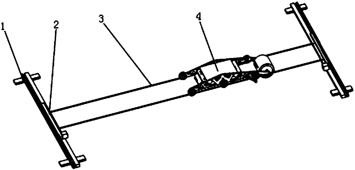
Figure 1 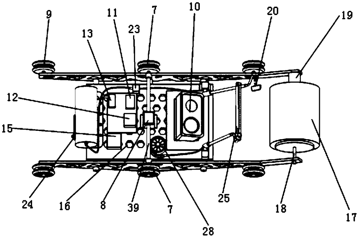
Figure 2 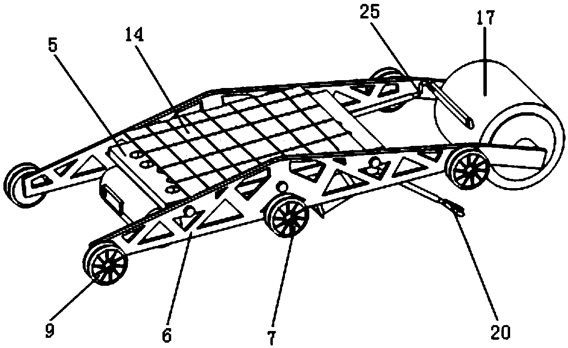
Figure 3
Abstract
Description
technical field
[0001] The invention belongs to the field of detection equipment, and more particularly relates to a sling type crack detection robot. Background technique
[0002] With the development of science and technology and the needs of production and life, people have built various large-scale engineering buildings, and the engineering buildings are dominated by concrete structures. Due to the stress and temperature changes of large-scale concrete building structures, their outer surfaces will change. Cracks, these cracks are the physical structure changes of the concrete structure due to the effect of internal and external factors, and are the main reason for the reduction of the bearing capacity, durability and water resistance of the concrete structure. Therefore, we need to identify whether the cracks are harmful cracks in time. For Harmful cracks must take corresponding safety measures in a timely manner. Traditionally, manual detection is usually used. Manual ...
Examples
Embodiment
[0074] figure 1 A structural schematic diagram of a sling-type crack detection robot according to an embodiment of the present invention is shown; figure 2 A schematic diagram of the bottom structure of a probe vehicle according to an embodiment of the present invention is shown; image 3 A schematic diagram of the top structure of a probe car according to an embodiment of the present invention is shown; Figure 4 shows a schematic structural diagram of a temperature changing device according to an embodiment of the present invention; Figure 5 A partial schematic diagram of a temperature changing device according to an embodiment of the present invention is shown; Figure 6 A schematic structural view of a hot air shower head according to an embodiment of the present invention is shown; Figure 7 It is a schematic diagram of the position of the snap ring according to an embodiment of the present invention; Figure 8 A schematic diagram of a control relationship according...