
Experimental test device for dry burning and melting of heating tube
A technology for testing equipment and heating tubes, which is applied in the direction of fuse testing, measuring electricity, and measuring devices. Exposure test, convenient dry burning fuse test, high safety test effect
Patent Information
- Authority / Receiving Office
- CN · China
- Current Assignee / Owner
- Publication Date
- 2019-01-11
- Estimated Expiration
- Not applicable · inactive patent
Smart Images
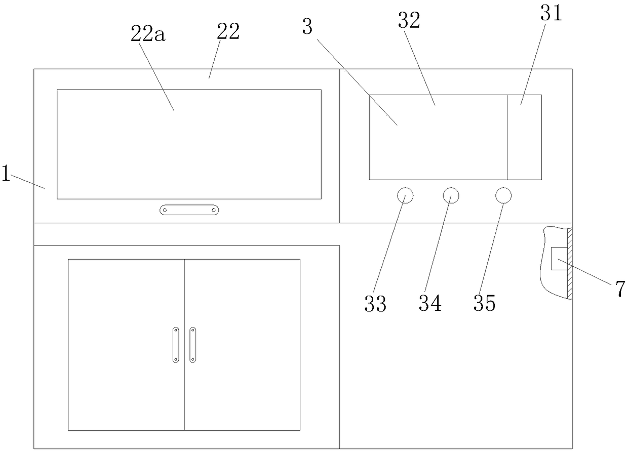
Figure 1 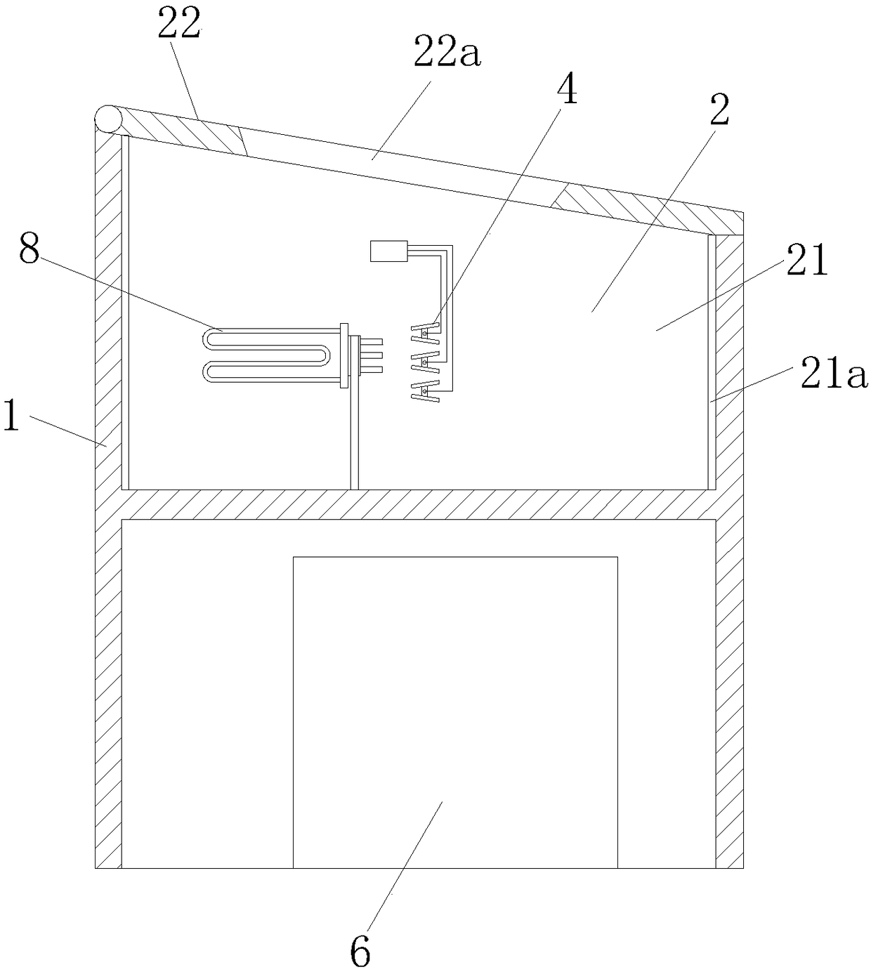
Figure 2 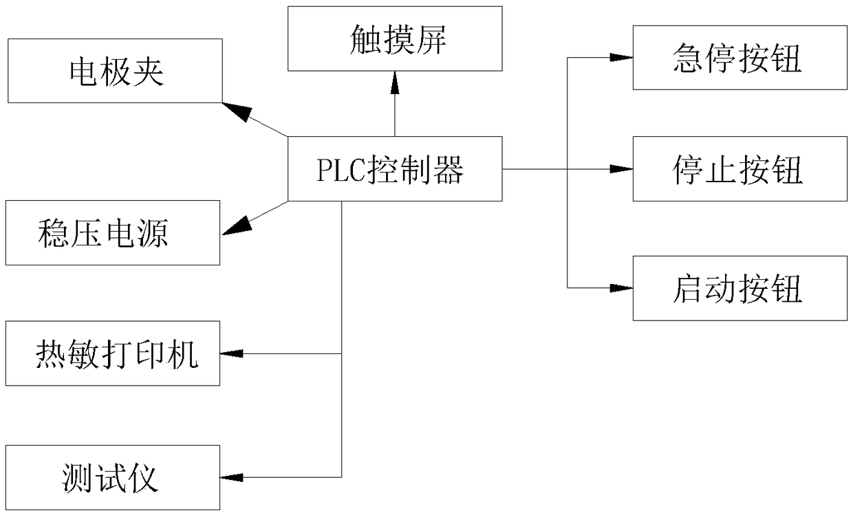
Figure 3
Abstract
Description
technical field
[0001] The invention relates to the technical field of heating tube testing, in particular to a heating tube dry-burning fusing experiment testing equipment. Background technique
[0002] At present, after the heating tube is processed, it is necessary to conduct a dry-burning fuse test. The existing test equipment is mostly split assembly equipment. The equipment uses a contact voltage regulator, a fuse tester and a set of detection aids. The reaction time of the dry-burning fuse is 50±20 seconds. After the fuse is blown, the withstand voltage and leakage current meet the requirements. Because the heating tube is exposed during the entire test process, it has certain safety hazards; the unstable voltage adjustment of the voltage regulator during the test will affect the test. As a result, the test data needs to be collected manually, and the operation is cumbersome, which is not conducive to the dry-burning fusing test of the heating tube. Contents of the ...
Examples
Embodiment Construction
[0019] In order to make the technical means, creative features, goals and effects achieved by the present invention easy to understand, the present invention will be further elaborated below.
[0020] Such as Figure 1 to Figure 3 As shown, a heating tube dry-burning fusing experiment test equipment includes a frame 1, a flame-retardant operation box 2 is provided on the left side of the frame 1, and a test system 3 is provided on the right side, and the test system 3 is connected with The electrode holder 4 located in the flame-retardant operation box 2, the tester 5 and the programmable power supply 6 located at the lower side of the frame 1, the tester 5 is used to test power, current and resistance, and the frame 1 is equipped with The test system 3 is connected to a thermal printer 7 for printing test data.
[0021] The flame retardant operation box 2 includes a box body 21 with an open top and made of sheet metal parts, a cover plate 22 that is matched with the opening ...