
Laser driving circuit and optical module
A laser drive and optical module technology, applied in circuits, lasers, laser parts and other directions, can solve the problem of lasers not working properly
Patent Information
- Authority / Receiving Office
- CN · China
- Current Assignee / Owner
- Publication Date
- 2019-01-18
Smart Images
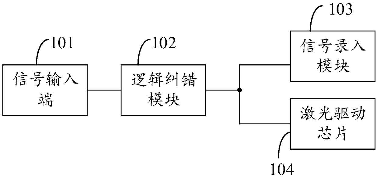
Figure 1 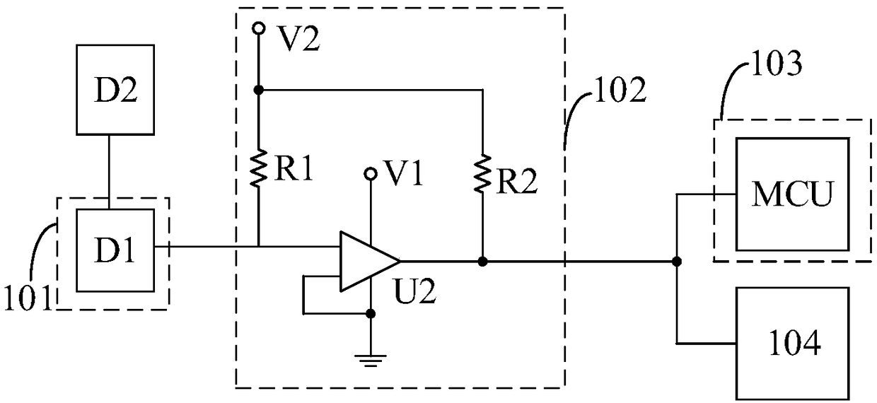
Figure 2
Abstract
Description
technical field
[0001] The invention relates to the technical field of power supply modules, in particular to a laser drive circuit and an optical module. Background technique
[0002] According to the SFF Committee (Small Form Factor Committee) SFF-8431 agreement, the small pluggable optical module transmit enable voltage is -0.3V ~ 0.8V, and the transmit disable voltage is 2V+0.3V, while the common The GN7151 10G laser driver chip’s enabling voltage is -0.3V~0.7V, and the disabling voltage is 1.2V+0.3V. In a conventional laser drive circuit, the enable / shutdown signal sent by the customer single board passes through the golden finger of the optical module and is directly connected to the laser drive chip to drive the laser to turn on or off, and is directly connected to the microprocessor to report the status. When it is greater than 0.7V and less than 0.8V, the laser driver chip does not work, and the laser has the risk of not emitting light, which is inconsistent with t...
Examples
Embodiment Construction
[0023] The following will clearly and completely describe the technical solutions in the embodiments of the present invention with reference to the accompanying drawings in the embodiments of the present invention. Obviously, the described embodiments are only part of the embodiments of the present invention, not all of them. Based on the embodiments of the present invention, all other embodiments obtained by persons of ordinary skill in the art without creative efforts fall within the protection scope of the present invention.
[0024] It should be noted that if there is a directional indication (such as up, down, left, right, front, back...) in the embodiment of the present invention, the directional indication is only used to explain the position in a certain posture (as shown in the accompanying drawing). If the specific posture changes, the directional indication will also change accordingly.
[0025] In addition, if there are descriptions involving "first", "second" and ...