
Anti-deformation flexible clamp for processing curved surface thin-walled parts and its clamping method
A technology for thin-walled parts processing and flexible fixtures, applied in the direction of manufacturing tools, metal processing equipment, metal processing machinery parts, etc., can solve the problems of poor surface effect, poor support rigidity, harmful to health, etc., and reduce manual clamping operation, ensure positioning accuracy, and improve the effect of clamping efficiency
Patent Information
- Authority / Receiving Office
- CN · China
- Patent Type
- Patents(China)
- Current Assignee / Owner
- Publication Date
- 2021-05-04
Smart Images
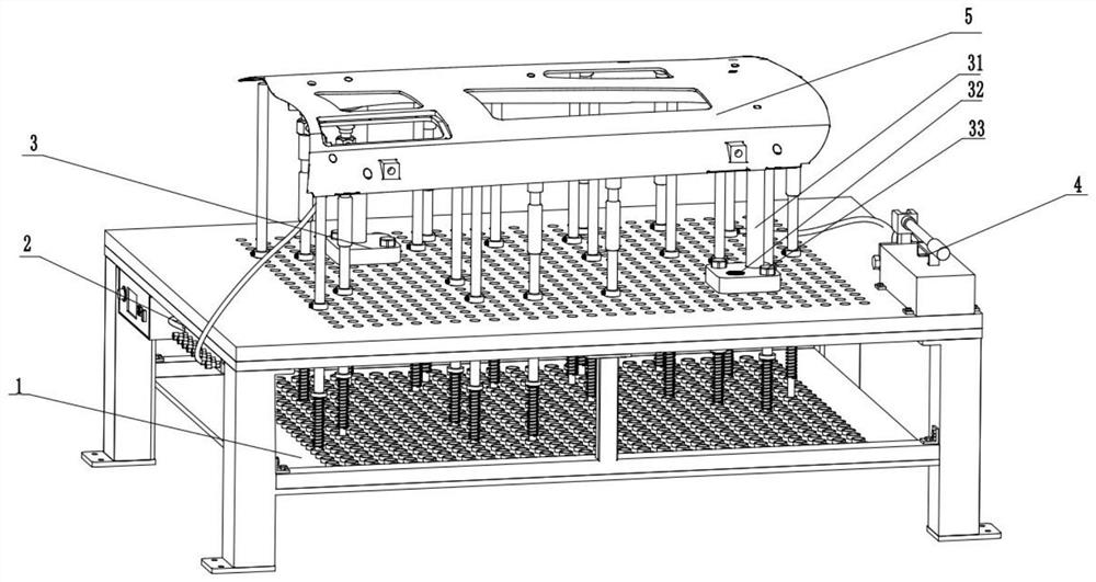
Figure 1 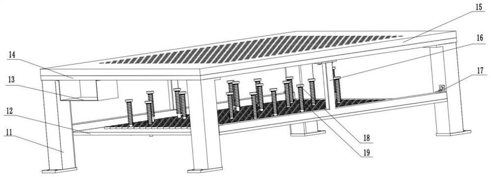
Figure 2 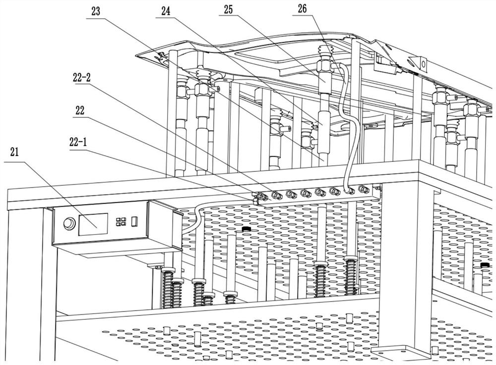
Figure 3
Abstract
Description
technical field
[0001] The invention belongs to the technical field of fixtures, in particular to a flexible anti-deformation fixture for processing curved surface thin-walled parts of an automobile main model. Background technique
[0002] Curved thin-walled parts are now more and more widely used in our industrial manufacturing industry. Most of the lines of the main car model adopt curved surface streamlined design. Curved thin-walled parts are easily deformed during the cutting process. If appropriate auxiliary supports are not used, it is difficult to guarantee the machining accuracy and quality of the parts. How to improve the machining accuracy of curved thin-walled parts has become the concern of most manufacturing companies. question. At present, curved thin-walled parts are generally processed by five-axis CNC machine tools, so it is necessary to optimize the clamping and auxiliary support of the workpiece to effectively prevent deformation of curved thin-walled p...
Examples
Embodiment Construction
[0039]The following will clearly and completely describe the technical solutions in the embodiments of the present invention with reference to the accompanying drawings in the embodiments of the present invention. Obviously, the described embodiments are only some, not all, embodiments of the present invention. Based on the embodiments of the present invention, all other embodiments obtained by persons of ordinary skill in the art without making creative efforts belong to the protection scope of the present invention.
[0040] see Figure 1-6 , the present invention provides a technical solution: an anti-deformation flexible clamp for processing curved surface thin-walled parts, which includes a clamp body 1, a vacuum suction cup clamping device 2, a positioning device 3 and a hydraulic locking device 4, wherein the positioning device The lower end of 3 is positioned and fixed on the clamp body 1 , and the upper end of the positioning device 3 is provided with a positioning pi...