
Process method of stamping forming of saw arm of swing saw
A stamping forming and process method technology, applied in the field of stamping process, can solve the problems of difficulty in improving the production efficiency of the swing saw saw arm, affecting the product quality, uneven force on the material plate, etc., so as to improve the forming quality, save the steps, reduce the Effects of Punch Time
Patent Information
- Authority / Receiving Office
- CN · China
- Patent Type
- Applications(China)
- Current Assignee / Owner
- Publication Date
- 2019-04-09
- Estimated Expiration
- Not applicable · inactive patent
Smart Images
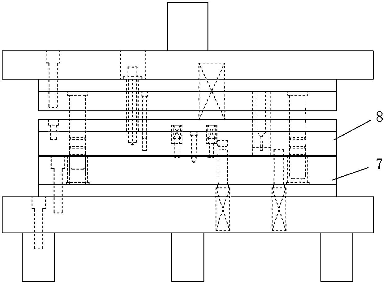
Figure 1 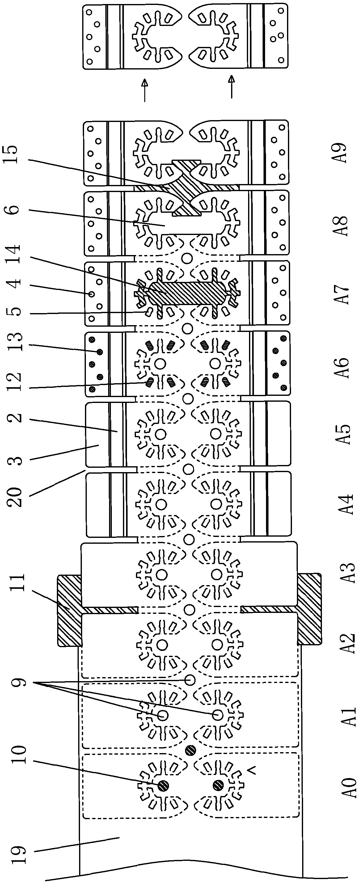
Figure 2 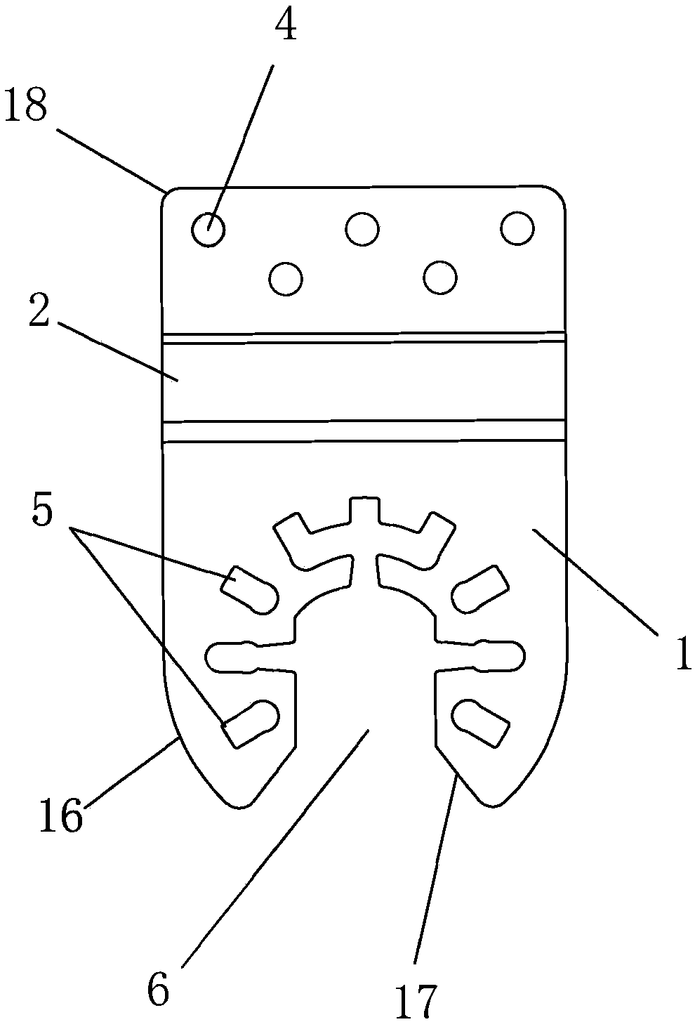
Figure 3
Abstract
Description
technical field
[0001] The invention relates to a stamping process, in particular to a process method for stamping the saw arm of an oscillating saw. Background technique
[0002] The saw arm of the swing saw is a board structure, as attached image 3 , attached Figure 4 As shown; in the conventional technology, it is generally made by stamping; but in the conventional technology, one piece is usually molded out, and the efficiency is not high; moreover, due to the structure of the swing saw arm, the middle hole area in the middle is larger, while the side During the stamping process, the plate body with a complete exterior is unevenly stressed, which can easily lead to local deformation and affect the quality of the product after stamping. Existing continuous punching technologies, such as the technologies disclosed in the name of "Rubber Plug Continuous Punching Die" (publication number: CN104552462A) and "pumping plate type stator and rotor piece continuous punching die...
Examples
Embodiment
[0026] Embodiment: The present invention a kind of technology method of stamping and forming of saw arm of swing saw, its forming process, as attached figure 2 shown; the mold used, as attached figure 1 shown. The specific method is:
[0027] On the stamping position, the punched two swing saw arms are arranged symmetrically up and down, and the mouths of the middle holes 6 of the two swing saw arms face each other; A0 pre-carry and A1-A9 nine progressive positions are arranged in sequence in the mold cavity ,in:
[0028] 1) A0 pre-carry punching guide hole 9;
[0029] 2) An edge trimming punch 11 is set up and down between the A2 and A3 grades to cut off the side edge of the material plate 19 and form the top edge of the substrate 1, wherein the A2 grade punching cuts off the right part (here the right The side part refers to the right side of the two-piece oscillating saw arm at the level of progress, not the right side of the finished product of the single-piece oscil...