
A screwdriver with slotting function and using method thereof
A screwdriver and functional technology, which is applied in the field of screwdrivers with slotting function, can solve the problems of fixed retaining sleeve, unstable slotting process, and inability of the knife bar to slot stably, so as to achieve the effect of avoiding rotation and stabilizing the process of unscrewing the screw
Patent Information
- Authority / Receiving Office
- CN · China
- Patent Type
- Patents(China)
- Current Assignee / Owner
- Publication Date
- 2020-09-04
Smart Images
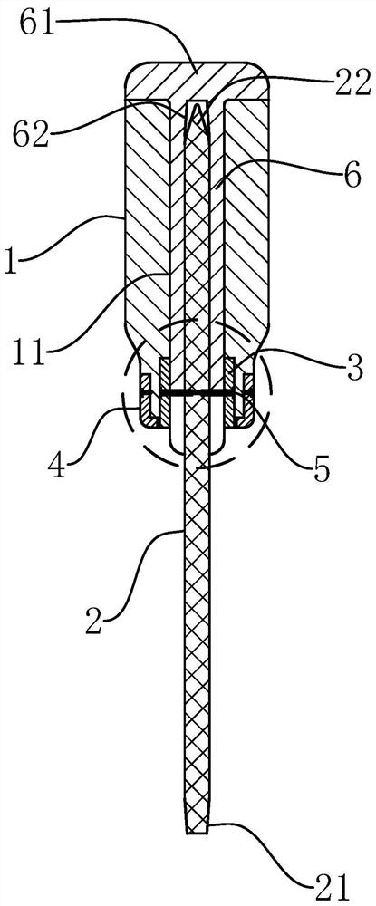
Figure 1 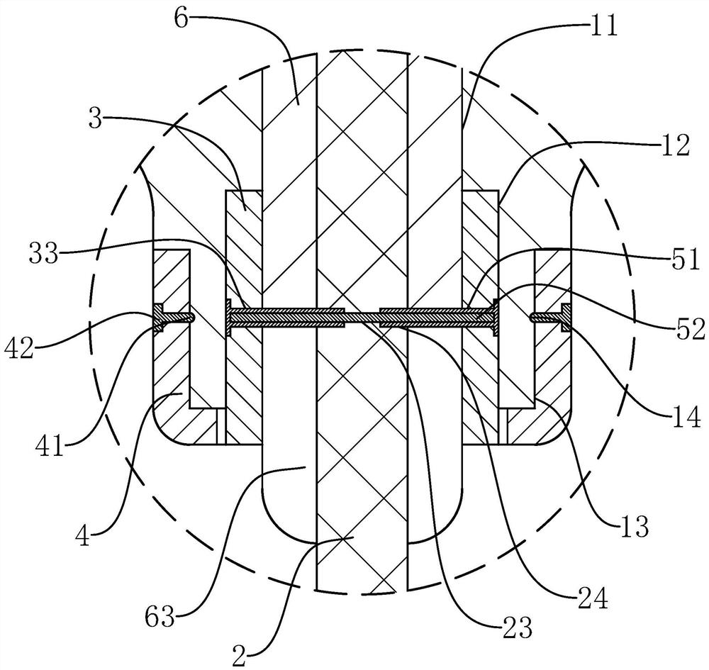
Figure 2 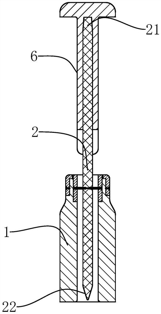
Figure 3
Abstract
Description
technical field
[0001] The invention belongs to the technical field of screwdrivers, and relates to a screwdriver with a slotting function and a using method thereof. Background technique
[0002] When the traditional screwdriver removes the screw, it is necessary to apply additional force to prevent the screwdriver bit from slipping off the thread groove. If the force is not enough, it will cause slippage. The existing application number is 201710332608.8, and the name is "an improved multi-functional screwdriver and Its method of use” Chinese invention patent, although it can use the auxiliary cutter head to make additional grooves on the thread groove to assist in unscrewing the screw when the screw cannot be opened after the thread slips. However, when it is used in practice, the following problems still exist:
[0003] 1. Since the auxiliary cutter head needs to move back and forth along the inline direction to make the groove when it grooves on the thread groove, so t...
Examples
Embodiment Construction
[0046] The following are specific embodiments of the present invention and in conjunction with the accompanying drawings, the technical solutions of the present invention are further described, but the present invention is not limited to these embodiments.
[0047] Such as Figure 1-5 As shown, a screwdriver with slotting function of the present invention comprises a knife handle 1 and a knife bar 2, and the front end and the rear end of the knife bar 2 respectively have a main cutter head 21 and an auxiliary cutter head 22 in a straight shape, and the auxiliary cutter head 22 The end has a sharp blade, and the handle 1 is coaxially provided with a rod hole 11, and the cutter rod 2 is penetrated in the rod hole 11, and the wall of the rod hole 11 is spaced from the wall of the cutter rod 2, and the front end hole of the rod hole 11 The wall is deepened to be provided with a regular polygonal groove-shaped inner adjustment groove 12, and also includes an inner adjustment sleeve...